Apparatus for making, handling, and filling pouches

a pouch and pouch technology, applied in the field of pouches for making, handling, and filling pouches, can solve the problems of high price, complex structure, and high cost of all such equipment, and achieve the effects of easy maintenance and operation, high price, and high pri

Inactive Publication Date: 2013-06-20
KHS GMBH
View PDF14 Cites 61 Cited by
  • Summary
  • Abstract
  • Description
  • Claims
  • Application Information

AI Technical Summary

Benefits of technology

[0015]It is therefore an object of the present invention to provide

Problems solved by technology

All such equipment is very expensive, very complex, very hard to maintain and operate and, above all, extremely difficult to adjust to pouches of different sizes.
It has the

Method used


Image

  • Apparatus for making, handling, and filling pouches
  • Apparatus for making, handling, and filling pouches
  • Apparatus for making, handling, and filling pouches

Examples


Embodiment Construction

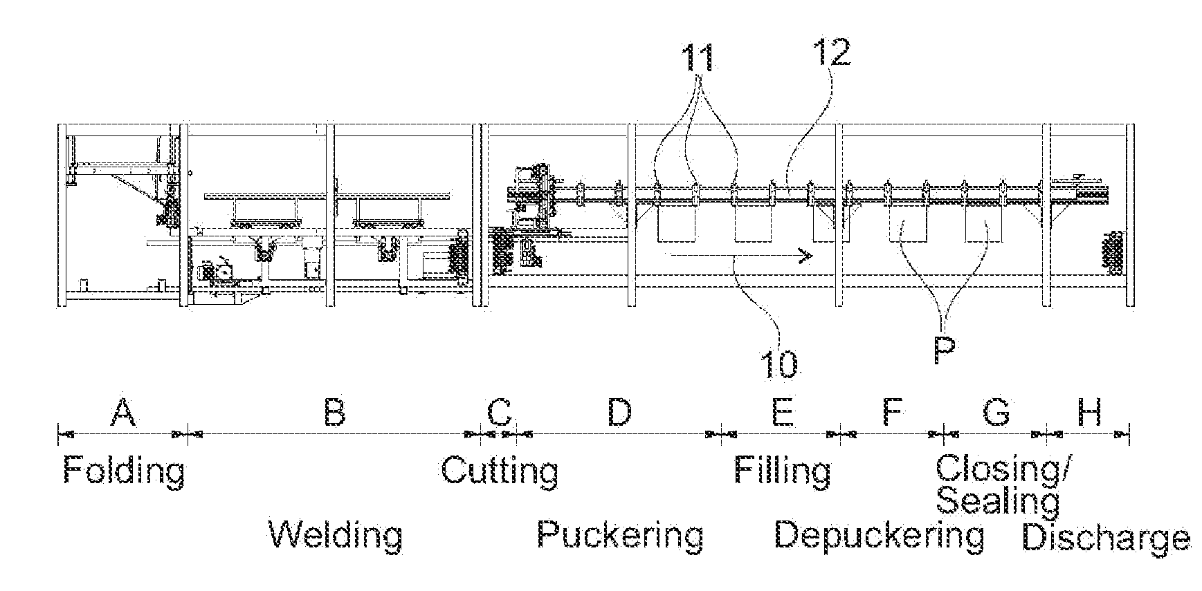
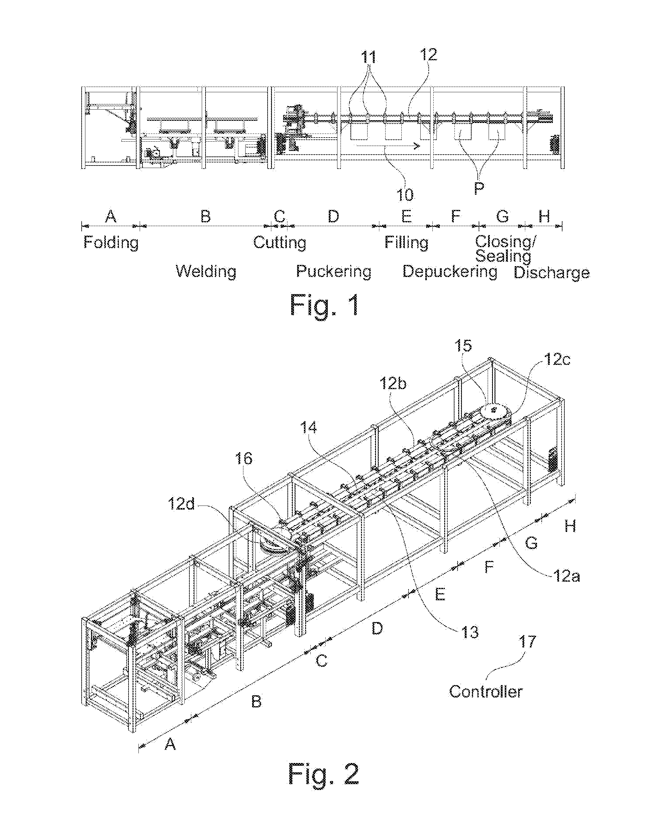
[0032]As seen in FIGS. 1 and 2 a machine according to the invention extends in a longitudinal travel direction 10 and has a folding station A, a welding station B, and a cutting station C as described in US 2010 / 0255372, whose disclosure is herewith incorporated by reference, together forming an intake station in which a sheet of plastic film is folded in half, then given a series of transversely throughgoing welds, and then cut into individual pouches P between the welds as is well known in the art. The individual pouches P are then oriented with their mouths directed upward and are each gripped between two longitudinally spaced carriage clamps 11 on a track 12 to proceed downstream in the direction 10.

[0033]As also indicated in FIGS. 7 and 8, in the puckering station D the trailing clamp 11 of each pair of pouch-suspending clamps 11 is accelerated slightly or the leading clamp 11 is decelerated, or both, so that the clamps 11 of each pair get closer together. At the same time unil...


PUM

PropertyMeasurementUnit
Speedaaaaaaaaaa
Transport propertiesaaaaaaaaaa

Abstract

A conveyor for a pouch-filling machine has an endless track with a working stretch and a return stretch extending from a downstream end of the working stretch to an upstream end of the working stretch. A plurality of carriages each carrying at least one permanent magnet and a clamp ride on the track for movement through the stations on the working stretch and for movement from the downstream end of the working stretch along the return stretch back to the upstream end of the working stretch. An array of electromagnets on the track only along the working stretch and an electronic controller connected to the electromagnets together constitute a frequency-controlled linear direct drive that advances the carriages downstream through the working stretch while varying the travel speeds of at least half of the carriages in the working stretch. A mechanical or frequency-driven conveyor is provided in the return stretch.

Description

FIELD OF THE INVENTION[0001]The present invention relates to an apparatus for making, handling, and filling pouches.BACKGROUND OF THE INVENTION[0002]A typical apparatus for producing packages each comprising a mass of granules or particles in a sealed plastic pouch typically has, spaced apart along a production path, an intake station, a pouch-puckering station, a pouch-depuckering station, a filling station, a sealing station, and a discharge station at a downstream end of the path.[0003]The intake station can simply receive premade pouches. Alternately at least partially thermoplastic synthetic-resin film is formed with a longitudinal fold then subdivided by pairs of transverse welds into a succession of normally rectangular pouches that are joined together and advanced longitudinally downstream as described in U.S. Pat. No. 6,272,815 whose entire disclosure is herewith incorporated by reference. The film constituting the pouches is typically made of polypropylene, polyethylene, m...

Claims


Application Information

Patent Timeline
IPC IPC(8): B65B7/02
CPCB65B9/087B65G54/02B65B7/02Y02P70/10
Inventor SAMMONS, MICHAELCALABRESE, ROGERWATMOUGH, OLIVER
Owner KHS GMBH
Why Eureka
Try Eureka