Apparatus for performing a plasma chemical vapour deposition process

a technology of chemical vapour deposition and apparatus, which is applied in the field of apparatus for performing a plasma chemical vapour deposition process, can solve the problems of introducing deviation to deposition targets, non-uniform lengthwise deposition near the end of the substrate tube, and worse microwave interaction effects, and achieves the effect of facilitating the existence of corresponding plasmas

Active Publication Date: 2013-06-20
DRAKA COMTEQ BV
View PDF10 Cites 2 Cited by
  • Summary
  • Abstract
  • Description
  • Claims
  • Application Information

AI Technical Summary

Benefits of technology

The invention is about a method for achieving even deposition of materials on a substrate using microwave energy. The method involves using multiple slit sections in the substrate tube, which allows the microwave energy to pass radially inward and generate plasmas in a balanced manner. This results in improved quality parameters like attenuation and uniformity of mode-field width. By adjusting the shift distance and mutual intensity difference between the plasmas, the method can achieve without oscillatory behavior and improve deposition efficiency.

Problems solved by technology

The cause of these variations is the microwave interaction of the resonator with the surrounding, mainly dominated by the metals shell around the furnace, which is needed for construction purposes and for prevention of high microwave leakage for health safety reasons.
The effect of the microwave interaction becomes even worse when the amount of deposited glass increases due to a cumulative effect and due to limited adaptive capabilities of the microwave configuration, like the efficiency of the chokes.
There can also be lengthwise deposition non-uniformity near the ends of the substrate tube due to reflections of microwave power, guided by the plasma at the tube, at the ends of the furnace.
A non-uniform microwave power along the length of the substrate tube causes a length / front position, relative to the resonator position, to change along the length of the substrate tube, thus introducing deviation to deposition targets based on the position of the resonator.
Furthermore, a moving furnace has an additional negative effect, because it decreases the effective core rod length by lowering the total resonator sledge pass length by a distance, which influences the fiber cost in a negative way.

Method used


Image

  • Apparatus for performing a plasma chemical vapour deposition process
  • Apparatus for performing a plasma chemical vapour deposition process
  • Apparatus for performing a plasma chemical vapour deposition process

Examples


Embodiment Construction

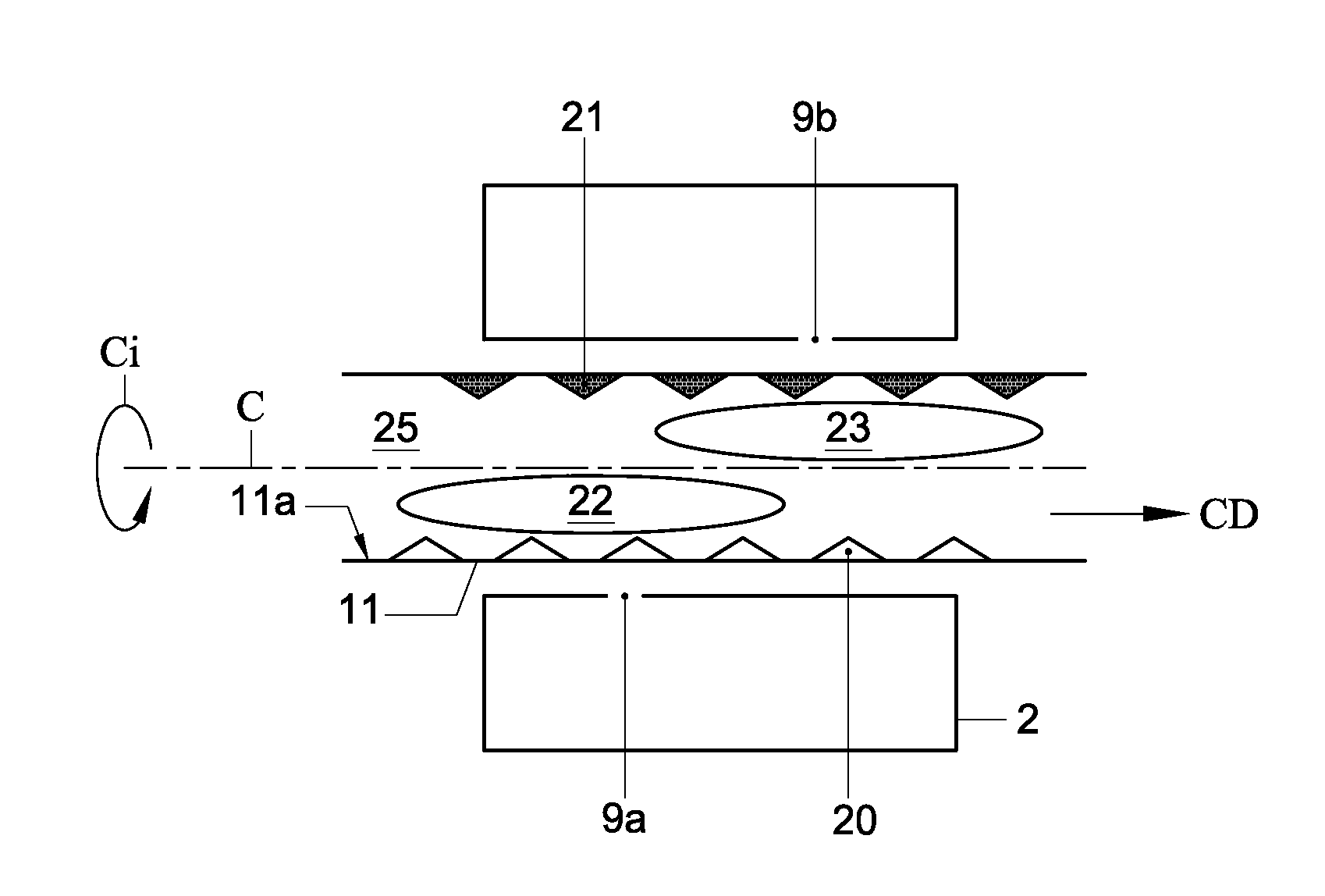
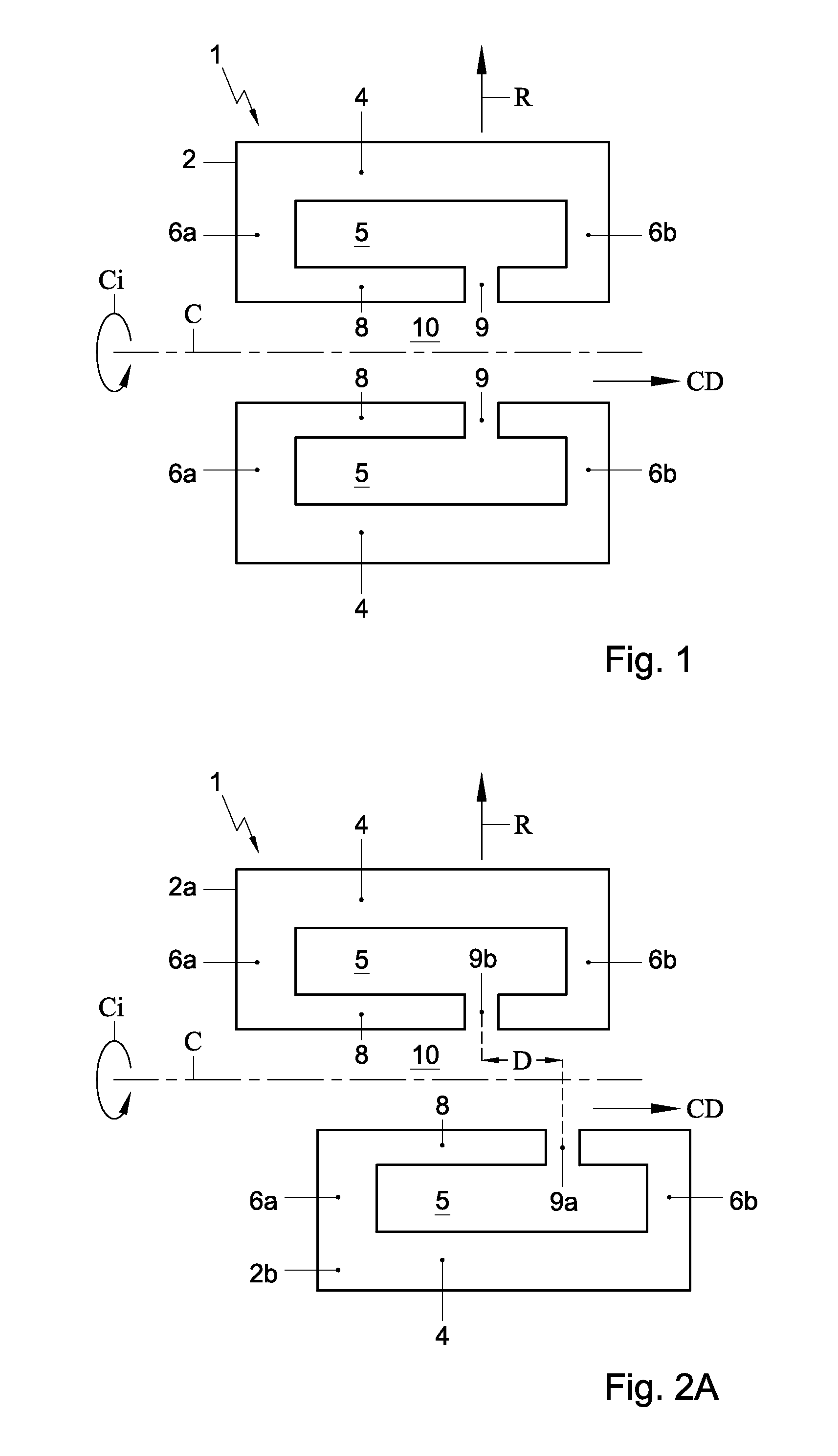
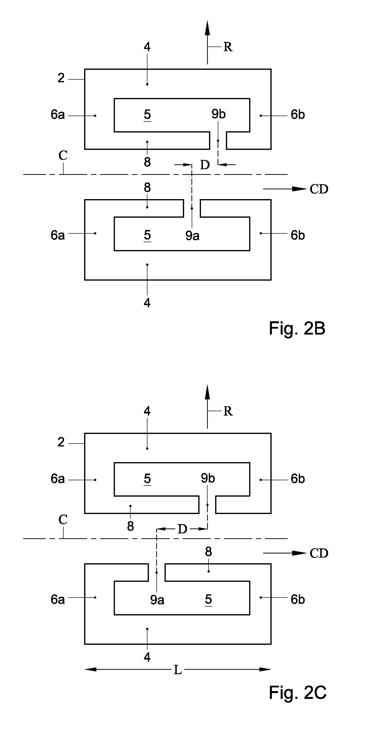
[0024]FIG. 1 shows a schematic cross sectional side view of a known apparatus for performing a plasma chemical vapour deposition process. The apparatus 1 comprises a mainly cylindrical resonator 2. The apparatus also comprises a microwave guide (not shown here) for guiding microwaves to the resonator 2. The microwave guide is preferably rectangular shaped so that an optimal interface between the guide and the resonator 2 can be made. The apparatus can be used for performing a plasma chemical vapour deposition process.

[0025]The resonator 2 is provided with an outer cylindrical wall 4 enclosing a resonant cavity 5. The cavity has a substantially rotational symmetric shape with respect to a cylindrical axis C. The resonator 2 is further provided with side wall portions 6a,b bounding the resonant cavity 5 in a cylindrical direction CD.

[0026]The resonator 2 further includes an inner cylindrical wall 8 bounding the resonance cavity 5 in a radial direction R towards the cylindrical axis C....


PUM

PropertyMeasurementUnit
Lengthaaaaaaaaaa
Lengthaaaaaaaaaa
Lengthaaaaaaaaaa

Abstract

The invention relates to an apparatus for performing a plasma chemical vapour deposition process. The apparatus comprises a mainly cylindrical resonator being provided with an outer cylindrical wall enclosing a resonant cavity extending in a circumferential direction around a cylindrical axis. The resonator is further provided with side wall portions bounding the resonant cavity in the cylindrical direction, and with a slit configuration extending in a circumferential direction around the cylindrical axis providing access from the resonant cavity radially inwardly. Further, the slit configuration includes slit sections that are mutually offset in the cylindrical direction.

Description

TECHNICAL FIELD[0001]The invention relates to an apparatus for performing a plasma chemical vapour deposition process, comprising a mainly cylindrical resonator being provided with an outer cylindrical wall enclosing a resonant cavity extending in a circumferential direction around a cylindrical axis, the resonator further being provided with side wall portions bounding the resonant cavity in the cylindrical direction, and with a slit configuration extending in a circumferential direction around the cylindrical axis providing access from the resonant cavity radially inwardly.BACKGROUND ART[0002]European patent publication EP 1 867 610 in the name of Draka Comteq B.V. discloses such an apparatus for manufacturing an optical fiber. In the plasma activated chemical vapour deposition (PCVD) process, deposition is performed on the inside of a substrate tube. In this process, the resonator is fed by a microwave source (typically a magnetron). Typically, the resonator moves back and forth ...

Claims


Application Information

Patent Timeline
IPC IPC(8): C23C16/511
CPCC23C16/511H01J37/32247C03B37/0183C23C16/513H05H1/24
Inventor MILICEVIC, IGORVAN STRALEN, MATTHEUS JACOBUS NICOLAASHARTSUIKER, JOHANNES ANTOON
Owner DRAKA COMTEQ BV
Why Eureka
Try Eureka