Golf ball mold and golf ball manufacturing method

Active Publication Date: 2013-06-20
BRIDGESTONE SPORTS
View PDF2 Cites 0 Cited by
  • Summary
  • Abstract
  • Description
  • Claims
  • Application Information

AI Technical Summary

Benefits of technology

[0012]It is therefore an object of the present invention to provide a golf ball mold which, particularly during formation of the outermost cover layer of a golf ball, minimizes abrasion of the mold body and support pins, thus extending the life of the mold, and also suppresses to the extent possible

Problems solved by technology

Satisfying all of these attributes with only one type of material is generally difficult.
However, when the center sphere 31 is placed in the mold 10 and the upper and lower mold halves are closed, the support pins 40 are often subjected to excessive forces, causing them to deflect or shift.
Hence, during molding, material entry is concentrated at places where the gap between the two is wide, as a result of which flash forms unevenly on the surface of the molded ball.
When uneven flash forms on the ball's surface, uniformly trimming the overall ball is not easy, making a clean appearance difficult to obtain.
Moreover, this may also lead to a loss of dimple uniformity and ultimately have an adverse effect on flight symmetry.
When molding cycles are repeated in s

Method used


Image

  • Golf ball mold and golf ball manufacturing method
  • Golf ball mold and golf ball manufacturing method
  • Golf ball mold and golf ball manufacturing method

Examples


Embodiment Construction

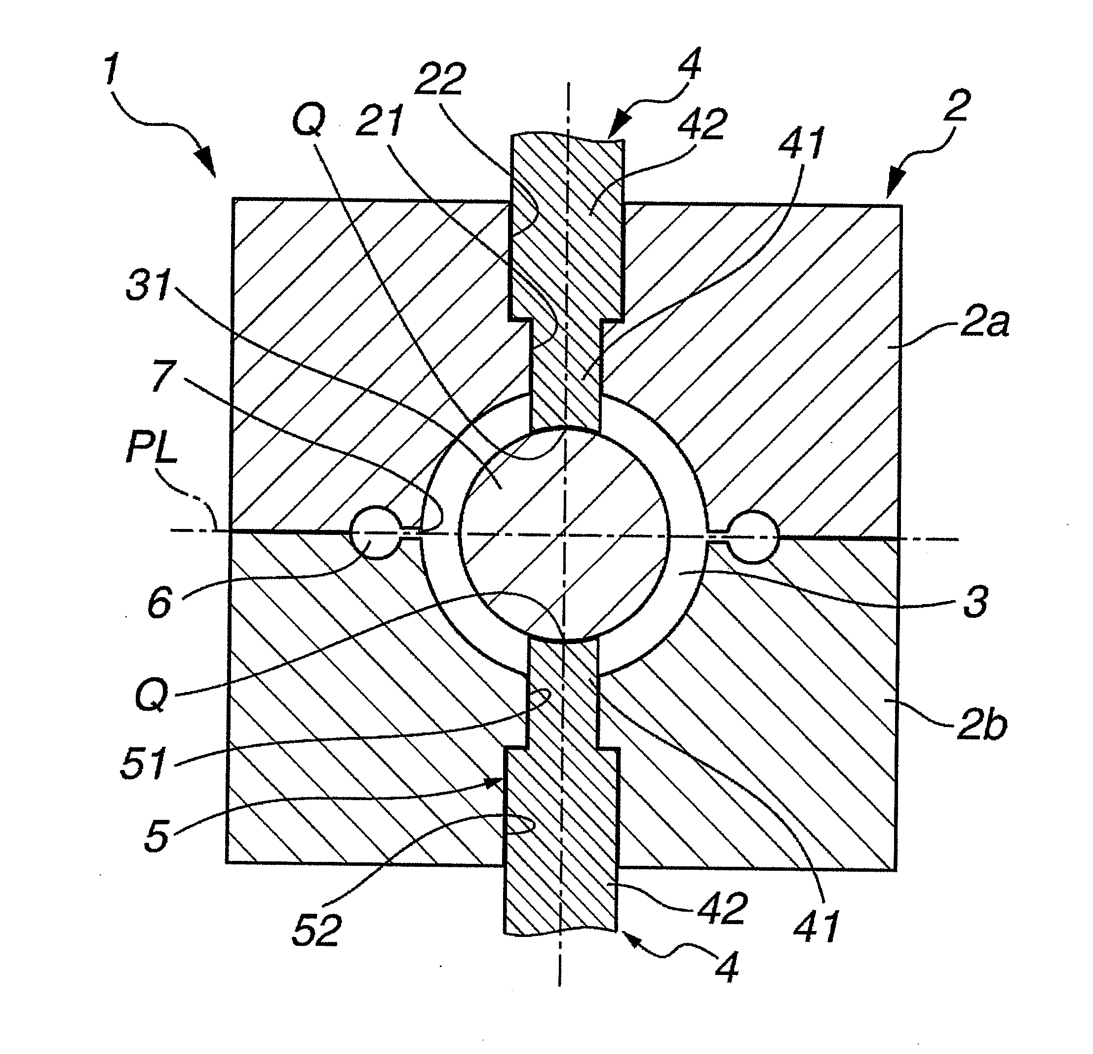
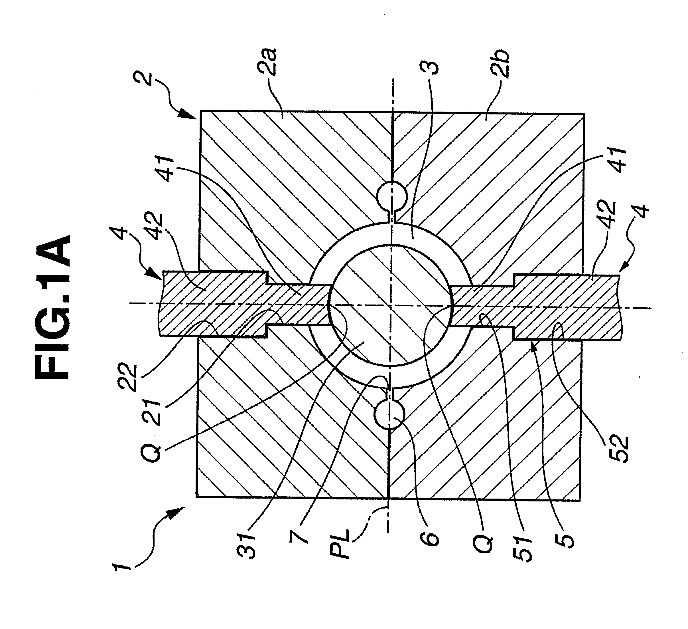
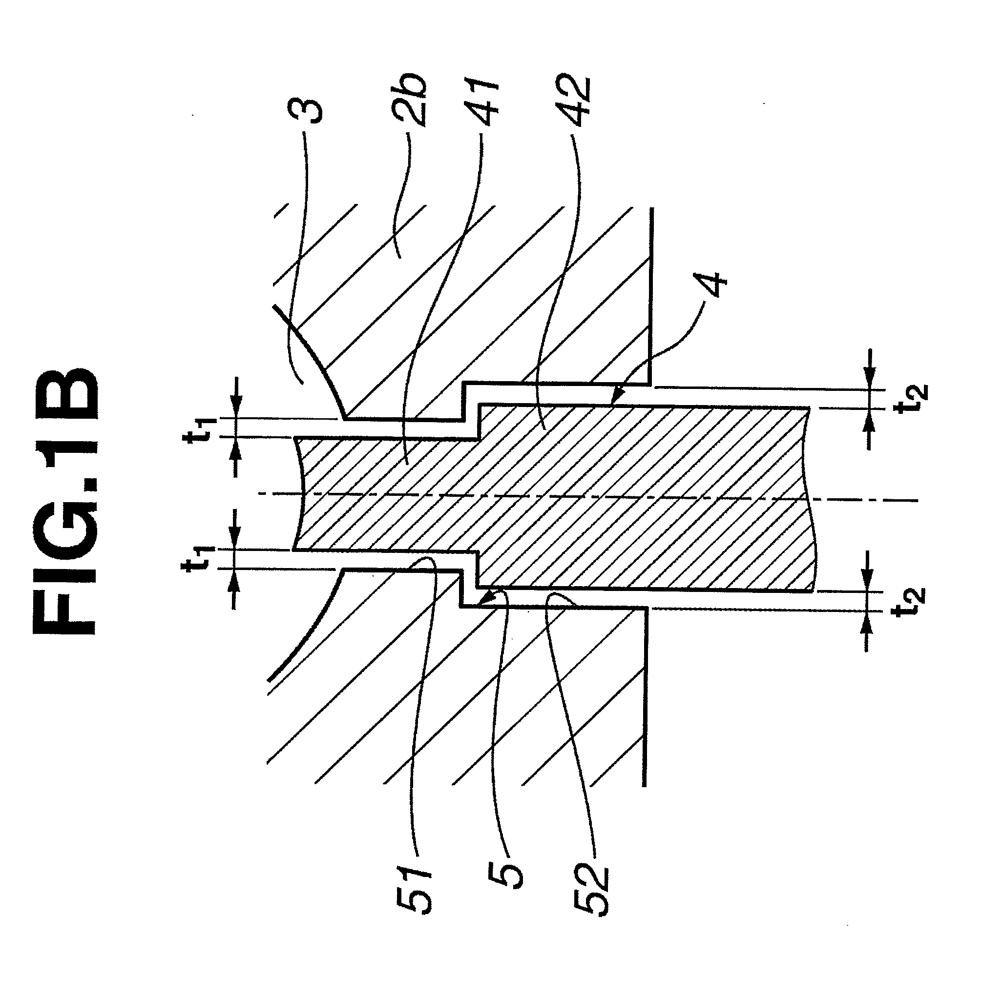
[0040]The golf ball mold of the invention is described more fully below in conjunction with the appended diagrams. The “parting line” and “parting surface” of the mold, as used in the description below, are defined as follows. The “parting line” is a line that serves as a reference when the mold splits into a plurality of parts. For example, in the case of a mold that splits into two parts, the parting line refers to a line that serves as a reference for the mating of the upper mold half with the lower mold half, and is rectilinear. The “parting surface” of the mold refers to the area of contact when the respective mold parts that have been separated based on the above parting line are joined together. In a case where dimple-forming protrusions which lie across the parting line are provided on the parting surface, the parting surface has convex features due to the dimple-forming protrusions and also has concave features which correspond to the convex features. In the present inventi...


PUM

PropertyMeasurementUnit
Latitudeaaaaaaaaaa

Abstract

A golf ball mold body having a plurality of mold parts with a parting surface defining a parting line along an equator and removably mating to form a cavity having an inner wall with dimple-forming protrusions, and a support pin extendable into and retractable from the cavity, the support pin extending into the cavity to support a center sphere. An end face of the support pin defines a portion of the cavity inner wall when the support pin is retracted. The support pin has a shape satisfying certain conditions, and the support pin and mold body have a gap therebetween set within a specific range. The invention minimizes formation of uneven flash caused by deflection or shifting of support pins, appearance defects caused by damage to the cavity inner wall and contamination by rubbing debris, and the life of the mold is extended.

Description

BACKGROUND OF THE INVENTION[0001]The present invention relates to a golf ball mold and a golf ball manufacturing method which may be suitably used for molding golf balls composed of a core encased by a cover of one, two or more layers, particularly for forming an outermost cover layer having a plurality of dimples formed on the surface thereof.[0002]In recent years, there has been a strong desire for various performance attributes in golf balls, including not only distance, but also controllability, durability and feel on impact. Satisfying all of these attributes with only one type of material is generally difficult. Hence, the customary practice is to provide the ball with a structure in which a solid core formed of rubber, resin or the like, or a wound core, is encased by a cover of one, two or more layers, each layer having a particular function. In other words, efforts have been made to achieve a performance which addresses the needs of the player, such as a desire primarily fo...

Claims


Application Information

Patent Timeline
IPC IPC(8): B29C45/14
CPCB29L2031/546B29C45/372B29C45/14819B29C45/14073
Inventor NAKAGAWA, TAKUMASATO, KATSUNORI
Owner BRIDGESTONE SPORTS
Why Eureka
Try Eureka