Liquid crystal display device

a liquid crystal display and display device technology, applied in non-linear optics, instruments, optics, etc., can solve the problems of insufficient effect, peeled thick alignment film, and bright spots, so as to prevent the scraping of alignment film caused by the contact between the columnar spacer and the pedestal, and prevent the positional displacement of the columnar spacer

Active Publication Date: 2013-06-20
JAPAN DISPLAY INC
View PDF11 Cites 27 Cited by
  • Summary
  • Abstract
  • Description
  • Claims
  • Application Information

AI Technical Summary

Benefits of technology

[0018]Further, the convex portion and the concave portion formed to the top end of the columnar spacer can be in various shapes. Further, two or more kinds of columnar spacers may be combined to provide a predetermined effect as a whole.
[0019]According to the invention, since the convex portion and the concave portion are disposed to the top end of the columnar spacer, and the concave portion is opened at the ends thereof and connected to the lateral side of the columnar spacer, the alignment film is not formed thick in the concave portion and, accordingly, scraping of the alignment film caused by the contact between the columnar spacer and the pede

Problems solved by technology

However, such effects were not obtained sufficiently in the related art.
However, this configuration results in a problem that the alignment film formed thick in the concave portion at the top of the columnar spacer is scraped off from a portion where the columnar spacer is in contact with the counter substrate, and the scraped dusts cause bright spots.
The technique described in JP-2009-25529-A results in a problem that the alignment film is formed thick in the concentric grooves formed at the top

Method used


Image

  • Liquid crystal display device
  • Liquid crystal display device
  • Liquid crystal display device

Examples


first embodiment

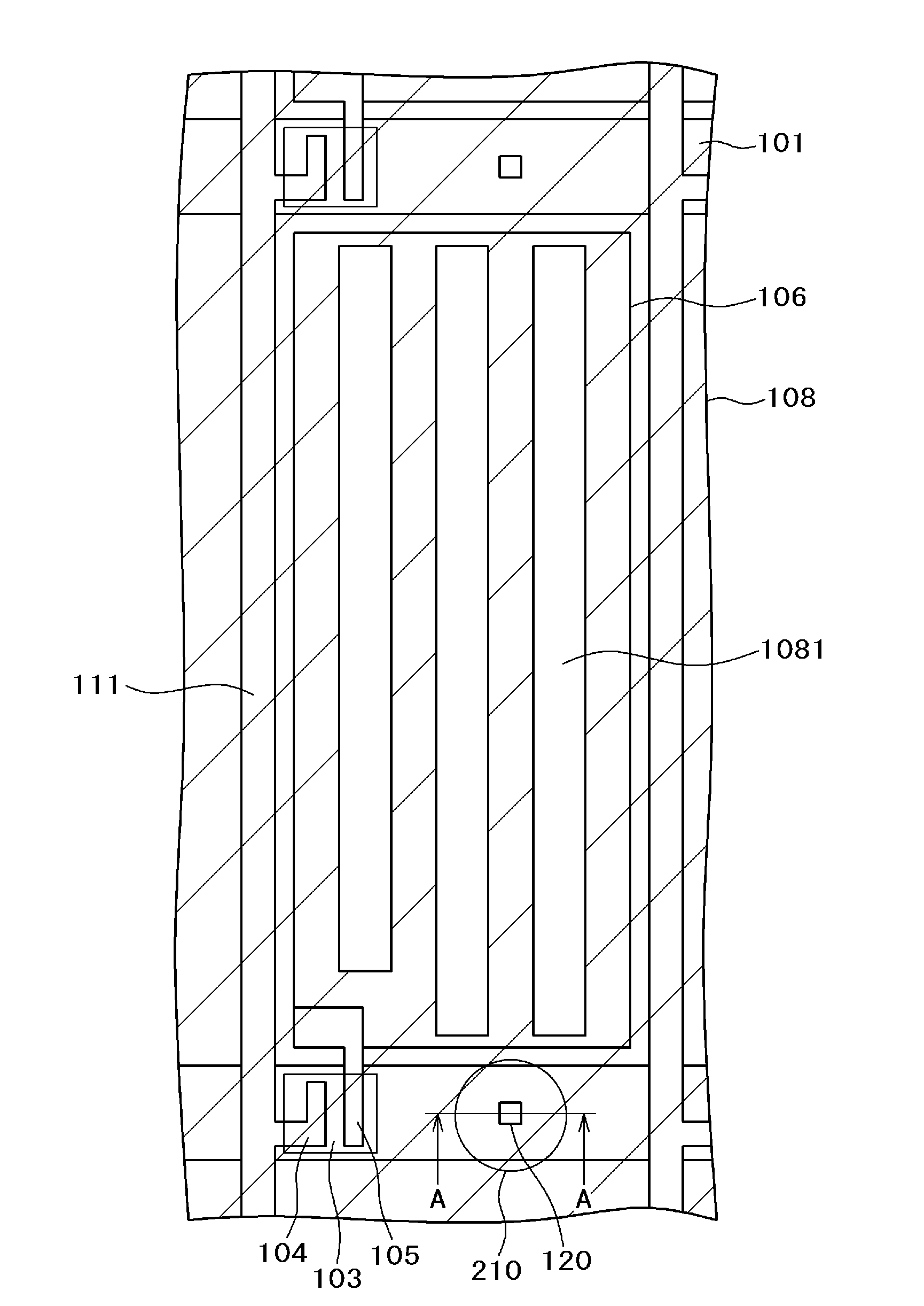
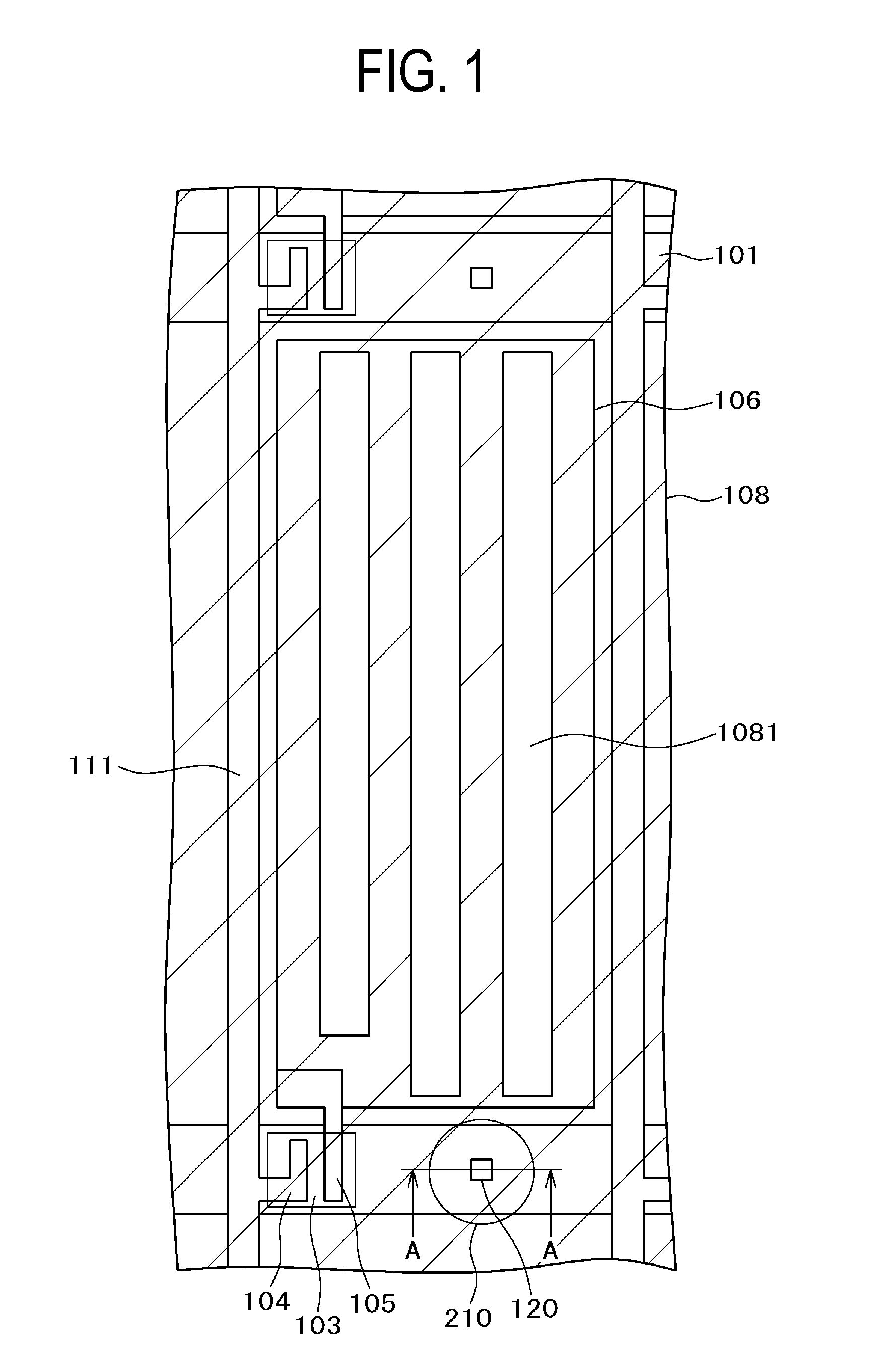
[0045]FIG. 1 is a plan view of a pixel portion of a liquid crystal display device to which the invention is applied. In FIG. 1, gate lines 101 are extended in a lateral direction and arranged in a longitudinal direction. Further, data lines 111 are extended in the longitudinal direction and arranged in the lateral direction. A pixel electrode 106 is formed in a region surrounded by the gate lines 101 and the data lines 111. The pixel electrode 106 is formed as a solid plane on which a not illustrated inorganic passivation film is stacked and a counter electrode 108 having slits 1081 is formed thereover. The counter electrode 108 is formed in common with each of pixels.

[0046]A semiconductor layer 103 is formed over the gate line 101, and a drain electrode 104 and a source electrode 105 are stacked over the semiconductor layer 103. The drain electrode 104 is branched from the data line 111, and the source electrode 105 is connected to the pixel electrode 106. When a voltage is supplie...

second embodiment

[0062]FIGS. 6 to 8 are views showing the shape and the arrangement of the columnar spacers 210 according to a second embodiment of the invention. FIG. 6 and FIG. 7 are plan views showing the state where the pedestal 120 intrudes to the concave portion 212 of the columnar spacer 210.

[0063]FIG. 6 shows a state in which a groove-shaped concave portion 212 opened at the ends thereof in the longitudinal direction, that is, in a y direction is formed on the top end of the columnar spacer 210. FIG. 7 shows a state in which a groove-shaped concave portion 212 opened at the ends thereof in the lateral direction, that is, in an x direction is formed on the top end of the columnar spacer 210.

[0064]In both of the columnar spacer 210 in FIG. 6 and the columnar spacer 210 in FIG. 7, since the concave portion 212 is opened at the ends and the liquid alignment film flows to the outside, the alignment film 190 is not formed thick in the concave portion 212. Accordingly, scraping of the alignment fil...

third embodiment

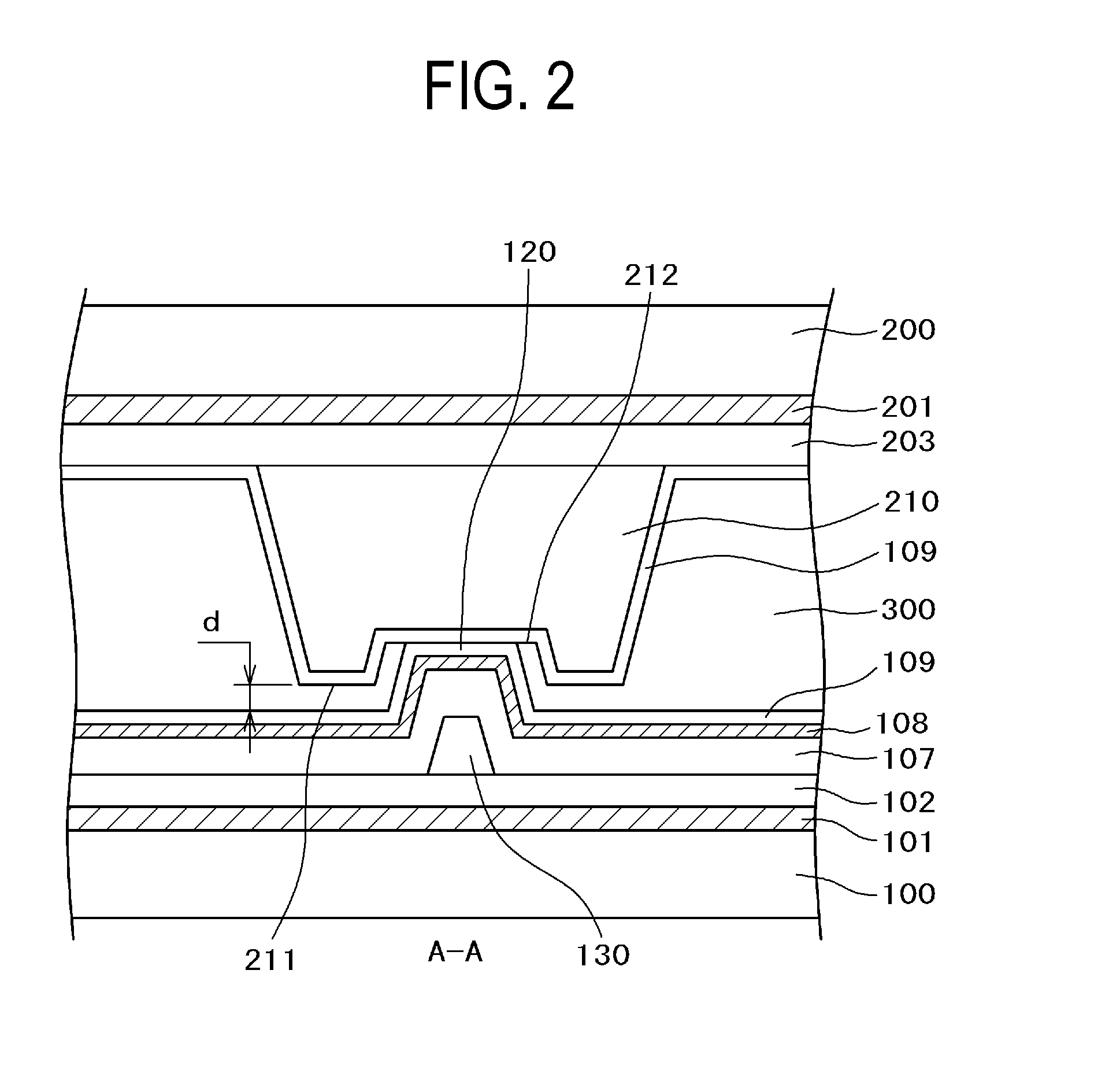
[0072]FIG. 12 is a cross sectional view showing a relation between a columnar spacer 210 and a pedestal 120. FIG. 13 is a plan view of a combination of the columnar spacer 210 and the pedestal 120 as viewed on the side of the TFT substrate 100. As shown in FIG. 12 and FIG. 13, a convex portion 211 and a concave portion 212 are formed each by one on the top end of the columnar spacer 210. The concave portion 212 is opened to the outside except for the side of the convex portion 211 and, accordingly, the material of the alignment film does not form a liquid reservoir. That is, the alignment film 109 is not formed thick in the concave portion 212.

[0073]In FIG. 12, a convex portion 211 and a concave portion 212 are formed at the top end of a columnar spacer 210. While the convex portion 211 is in contact with the TFT substrate 100, the pedestal 120 formed on the TFT substrate 100 is not in contact with the concave portion 212 at the top end of the columnar spacer 210. When an external f...


PUM


Abstract

A liquid crystal display device includes: a TFT substrate having gate lines and data lines arranged thereon, the gate lines extending in a first direction and arranged in a second direction, the data lines extending in the second direction and arranged in the first direction; a counter substrate having a black matrix and a color filter; and liquid crystals put between the TFT substrate and the counter substrate. Columnar spacers are formed on the counter substrate. Pedestals are formed on portions of the TFT substrate, the portions corresponding to the columnar spacers. A convex portion and a concave portion are present at the top end of the columnar spacer. The pedestal is formed corresponding to the concave portion. The concave portion is opened at the ends thereof and connected to the lateral side of the columnar spacer.

Description

CLAIM OF PRIORITY[0001]The present application claims priority from Japanese Patent Application JP 2011-277234 filed on Dec. 19, 2011, the content of which is hereby incorporated by reference into this application.BACKGROUND OF THE INVENTION[0002]1. Field of the Invention[0003]The present invention relates to a liquid crystal display device. The invention particularly relates to a liquid crystal display device taking measures to prevent bright spots caused by scraped dusts of an alignment film.[0004]2. Description of the Related Art[0005]Liquid crystal display devices include: a TFT substrate having pixel electrodes, thin film transistors (TFT), etc. formed in a matrix; a counter substrate disposed in facing relation to the TFT substrate and having color filters, etc. formed at positions corresponding to the pixel electrodes of the TFT substrate; and liquid crystals put between the TFT substrate and the counter substrate. Images are formed by controlling the light transmittance of l...

Claims


Application Information

Patent Timeline
IPC IPC(8): G02F1/1339
CPCG02F1/1339G02F2001/13398G02F1/13394G02F1/13398G02F1/136286G02F1/1368G02F1/13396
Inventor TOMIOKA, YASUSHIKUNIMATSU, NOBORUHYODO, YOSUKEKANEKO, TOSHIKIMATSUMOTO, YUKO
Owner JAPAN DISPLAY INC
Why Eureka
Try Eureka