Exposure apparatus and exposure method

a technology of exposure apparatus and exposure method, which is applied in the field of exposure technology, can solve the problems of limited electrical products performance, achieve the effect of promoting the performance of electrical devices, reducing the line space of desired patterns, and high depth-to-width ratio

Active Publication Date: 2013-06-20
SHENZHEN CHINA STAR OPTOELECTRONICS TECH CO LTD
View PDF6 Cites 2 Cited by
  • Summary
  • Abstract
  • Description
  • Claims
  • Application Information

AI Technical Summary

Benefits of technology

[0015]With the use of the exposure apparatus and the exposure method of the present invention, it can be ensured that an exposed portion of the photo-resist layer can be patterned completely, so as to prevent that the photo-resist layer can not be expose sufficiently due to a small line space or a high depth-to-width ratio. Therefore, by means of the exposure apparatus and the exposure method of the present invention, the line space of the desired pattern can be reduced for promoting the performance of electrical devices.

Problems solved by technology

However, when a line space of a pattern of the photo-resist is too small, the photo-resist has a lower transmittance, and thus a portion of the photo-resist is not exposed and is still non-patterned.
Therefore, after the photo-lithography process, the formed pattern can not meet the requirement of a predetermined pattern, and the performance of the electrical products is limited.

Method used


Image

  • Exposure apparatus and exposure method
  • Exposure apparatus and exposure method
  • Exposure apparatus and exposure method

Examples


Embodiment Construction

[0022]The following embodiments are referring to the accompanying drawings for exemplifying specific implementable embodiments of the present invention. Furthermore, directional terms described by the present invention, such as upper, lower, front, back, left, right, inner, outer, side and etc., are only directions by referring to the accompanying drawings, and thus the used directional terms are used to describe and understand the present invention, but the present invention is not limited thereto.

[0023]In the drawings, structure-like elements are labeled with like reference numerals.

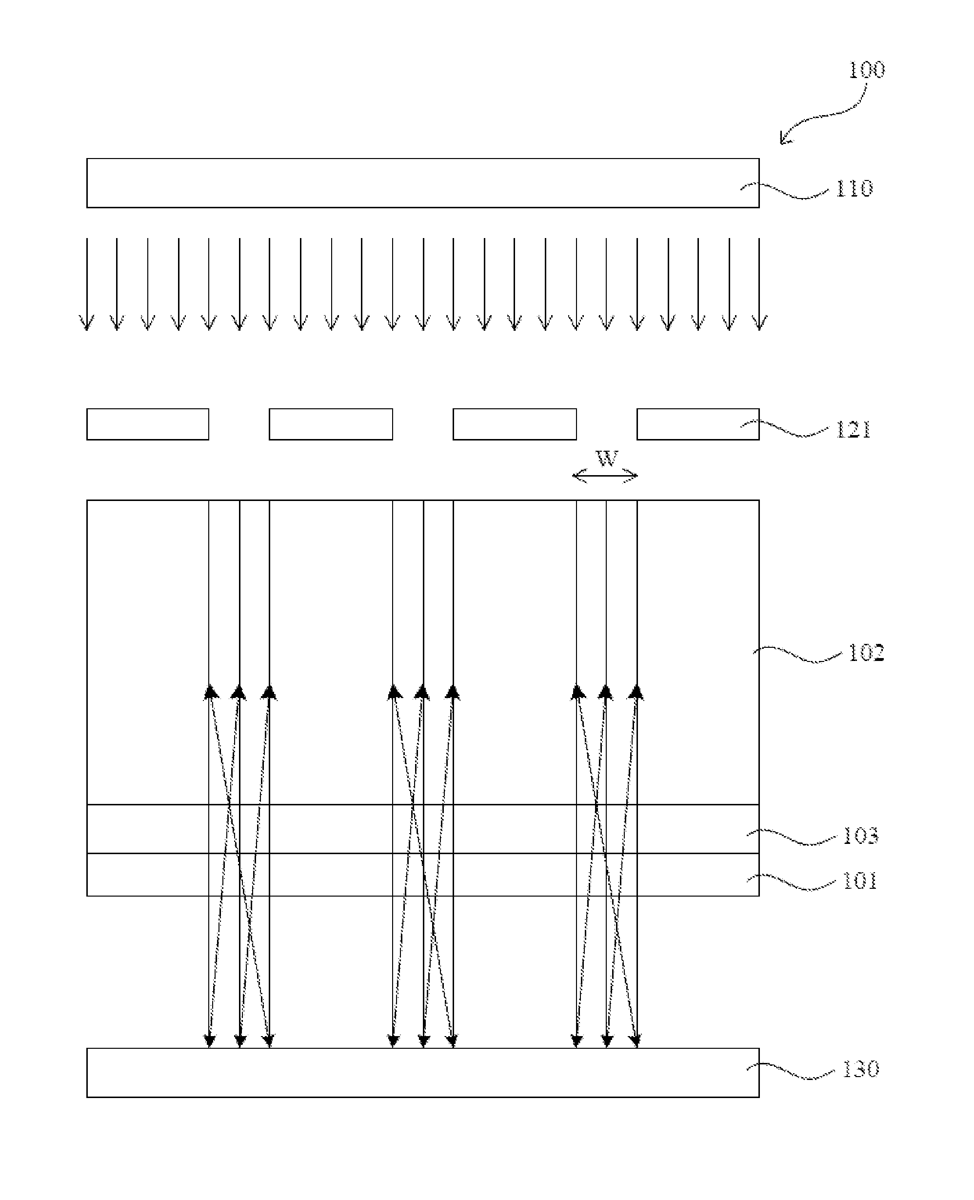
[0024]Referring to FIG. 1, a schematic diagram showing an exposure apparatus according to a first embodiment of the present invention is illustrated. The exposure apparatus 100 of the present invention is configured to expose a photo-resist layer 102 on a transparent substrate 101 for patterning the photo-resist layer 102. In this case, the transparent substrate 101 may be a transparent glass substrate...


PUM


Abstract

The present invention provides an exposure apparatus and an exposure method. The method comprises: utilizing an exposure light source to provide light rays to the photo-resist layer; and utilizing a reflective plate to reflect the light rays passing through the photo-resist layer and the transparent substrate back to the photo-resist layer. The present invention can reduce a line space of a pattern of the photo-resist layer.

Description

FIELD OF THE INVENTION[0001]The present invention relates to a field of an exposure technology, and more particularly to an exposure apparatus and an exposure method.BACKGROUND OF THE INVENTION[0002]A photo-lithography technology has been widely applied in manufacturing processes of electrical products. With the use of the photo-lithography technology, a photo-resist is exposed to form different patterns. However, when a line space of a pattern of the photo-resist is too small, the photo-resist has a lower transmittance, and thus a portion of the photo-resist is not exposed and is still non-patterned. Therefore, after the photo-lithography process, the formed pattern can not meet the requirement of a predetermined pattern, and the performance of the electrical products is limited.[0003]Specifically, in many current electrical devices, such as liquid crystal displays (LCDs), the line space of the pattern thereof is required to be reduced continuously for promoting the performance of ...

Claims


Application Information

Patent Timeline
Patent Type & Authority Applications(United States)
IPC IPC(8): G03B27/42
CPCG03F7/2032G03F7/70325
Inventor HSU, JEHAOSHIH, MINGHUNGXUE, JINGFENG
Owner SHENZHEN CHINA STAR OPTOELECTRONICS TECH CO LTD
Why Eureka
Try Eureka