Check patentability & draft patents in minutes with Patsnap Eureka AI!

Lighting Fixture

a technology for lighting fixtures and fixtures, applied in the field of lighting fixtures, can solve the problems of inconvenient use of incandescent and halogen bulbs, inconvenient installation, and high energy consumption of incandescent light bulbs, and achieve the effect of simple heat dissipation mechanism

Active Publication Date: 2013-06-20
ALSI HLDG LLC
View PDF6 Cites 7 Cited by
  • Summary
  • Abstract
  • Description
  • Claims
  • Application Information

AI Technical Summary

Benefits of technology

The solution provides efficient light distribution at a distance using fewer LEDs, extending their lifespan and reducing energy costs by effectively managing heat, making LEDs a viable option for streetlights and office lighting.

Problems solved by technology

The use of incandescent and halogen bulbs has been problematic in a number of ways.
First, incandescent light bulbs are very energy inefficient.
Although fluorescent bulbs are more efficient than incandescent light bulbs, fluorescent bulbs raise environmental concerns, and are still very inefficient when compared to LEDs or other similar solid state light emitters.
Additionally, incandescent and fluorescent light bulbs have short life spans when compared to solid state emitters.
Such short life spans are particularly more problematic when used in overhead lighting in office buildings or in streetlights, where access may be difficult.
Replacement is not only time consuming, but can be dangerous.
Furthermore, the unwanted heat produced in these lighting systems adds not only to additional energy costs but may also requires additional air conditioning to lower the temperature of the area lit by the system.
Although solid state emitters, such as LEDs, are known to be more energy efficient, LEDs have not been considered in the past as an option for providing quality light in many applications, such as streetlights and office lighting systems, because LEDs do not provide enough useful light at a distance.
Moreover, LEDs are a new technology, and therefore are more expensive.
However, the use of LEDs in such lighting fixtures typically requires a large number of LEDs clustered closely together to provide useful light output.
Accordingly, lighting fixtures incorporating LEDs in this manner generate a large amount of heat energy when the LEDs emit light.
If this heat energy is not effectively removed, the high temperature caused by the heat energy will reduce the luminance and life span of the LEDs.
Therefore, each of the foregoing-described lighting fixtures requires a complex heat dissipating mechanism to adequately remove the heat energy produced by the large number of LEDs.

Method used


Image

  • Lighting Fixture
  • Lighting Fixture
  • Lighting Fixture

Examples


Embodiment Construction

[0053]For purposes of the description hereinafter, spatial orientation terms, as used, shall relate to the referenced embodiment as it is oriented in the accompanying drawing figures or otherwise described in the following detailed description. However, it is to be understood that the embodiments described hereinafter may assume many alternative variations and configurations. It is also to be understood that the specific devices, features, and components illustrated in the accompanying drawing figures and described herein are simply exemplary and should not be considered as limiting.

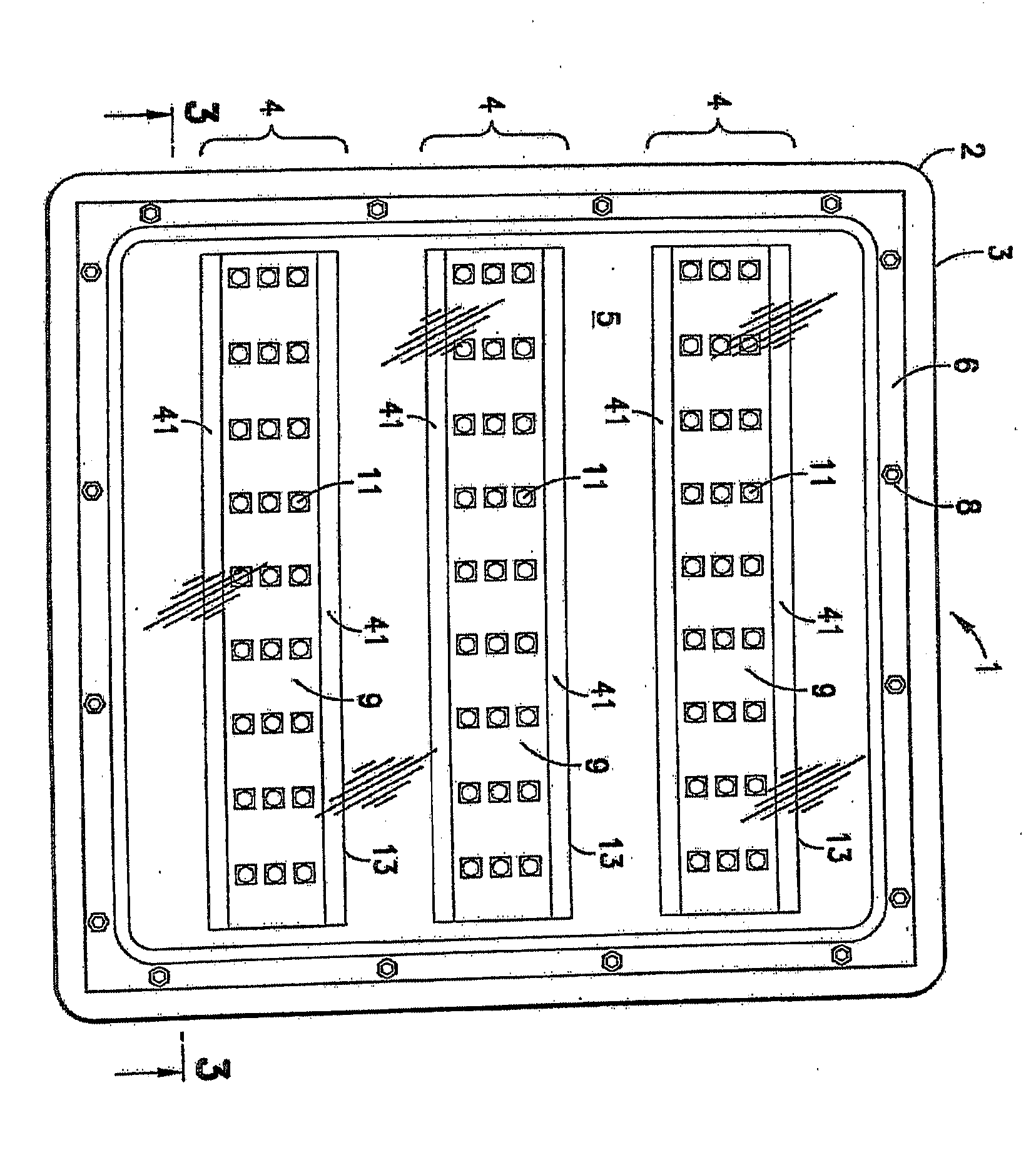
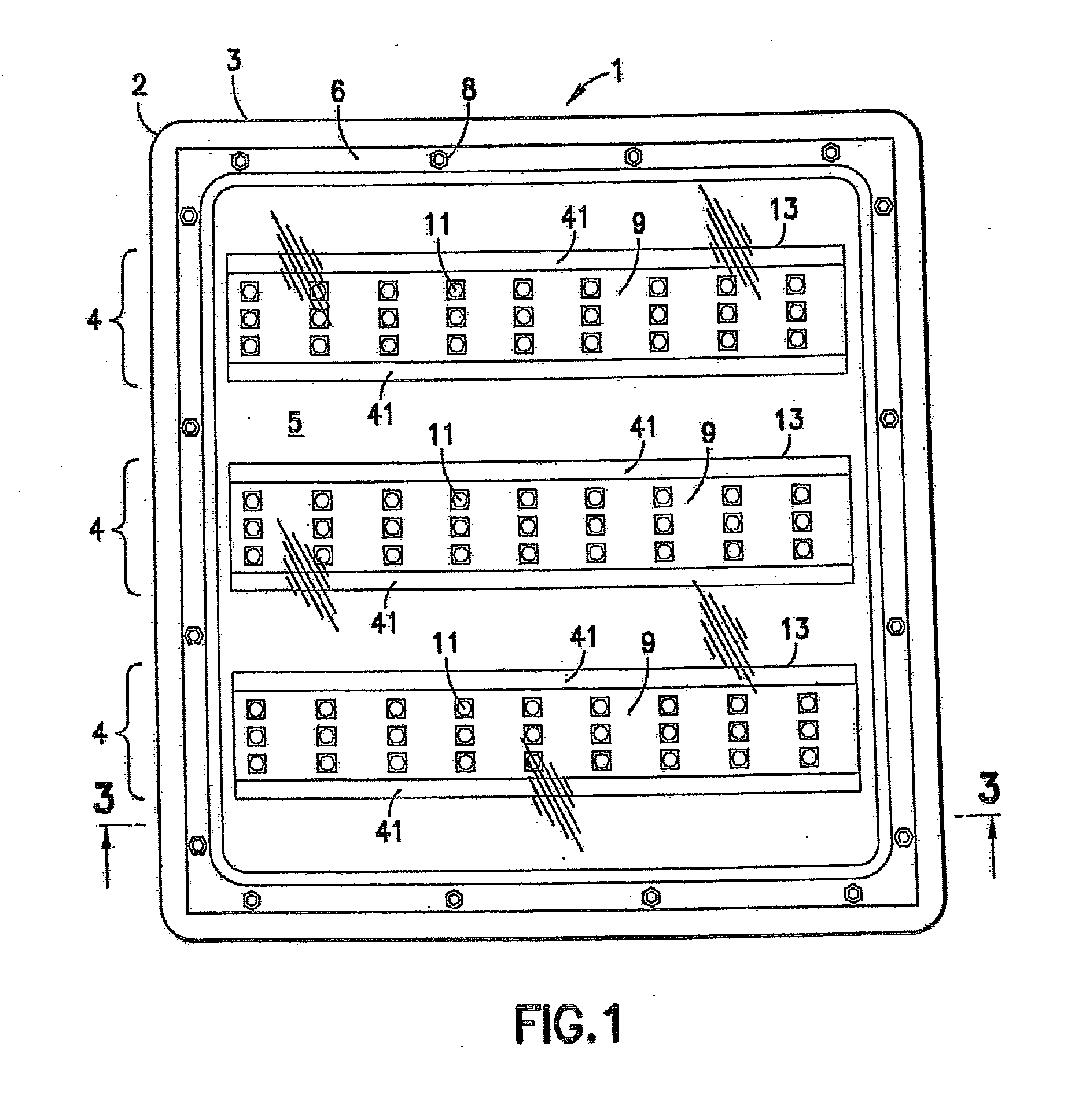
[0054]Generally speaking, an embodiment of the present invention involves a lighting arrangement incorporating one or more lighting strips comprising a plurality of light emitting diodes LEDs to provide a light emitting sub-assembly or device. A lighting fixture may be provided that incorporates the LED lighting strips and desirably utilizes a shell or housing assembly of the lighting fixture as an integ...


PUM

PropertyMeasurementUnit
heightaaaaaaaaaa
heightaaaaaaaaaa
heightaaaaaaaaaa

Abstract

A light emitting diode (LED) lighting arrangement for a lighting fixture includes: a lighting strip comprising a plurality of light emitting diodes (LEDs) arranged along a length of the lighting strip; a first multi-faceted side wall reflector extending from a first side of the lighting strip at an angle such that the first multi-faceted side wall reflector extends along an entire length of the lighting strip and away from a bottom portion of a light emitting portion of each of the light emitting diodes (LEDs); and a second multi-faceted side wall reflector extending from a second, opposite side of the lighting strip at an angle such that the second multi-faceted side wall reflector extends along an entire length of the lighting strip away from the bottom portion of the light emitting portion of each of the light emitting diodes (LEDs). The first and second multi-faceted side wall reflectors cause light produced by the plurality of light emitting diodes (LEDs) to be amplified and formed into a uniform beam.

Description

CROSS REFERENCE TO RELATED APPLICATIONS[0001]This application is a continuation of U.S. patent application Ser. No. 12 / 341,798, filed Dec. 22, 2008, which claims the benefit of U.S. Provisional Patent Application No. 61 / 015,713 entitled “Lighting Fixture” filed Dec. 21, 2007, U.S. Provisional Patent Application No. 61 / 094,558 entitled “Lighting Fixture with Improved Cover and Mounting Assembly” filed Sep. 5, 2008 and U.S. Provisional Patent Application No. 61 / 094,571 entitled “Reflectors for Use with a Lighting Fixture” filed Sep. 5, 2008, which are all hereby incorporated by reference in their entirety.BACKGROUND OF THE INVENTION[0002]1. Field of the Invention[0003]The present invention relates, in general, to lighting fixtures (luminaires) that utilize light emitting diodes (LEDs) as a light source and, more particularly, to lighting fixtures incorporating LEDs configured in a manner to amplify and direct light produced by such lighting fixtures.[0004]2. Description of Related Art...

Claims


Application Information

Patent Timeline
Patent Type & Authority Applications(United States)
IPC IPC(8): F21V7/00H05B44/00
CPCF21V7/00Y02B20/72F21Y2103/003F21V7/048F21V7/005F21V17/164F21Y2113/00F21Y2101/00F21Y2105/10F21Y2103/10F21Y2115/10F21V7/28Y02B20/40H05B47/195H05B45/12H05B45/10H05B47/19H05B47/11H05B47/16F21V7/22F21V29/74F21S8/026F21S8/086F21V23/04F21W2131/103
Inventor WASSEL, JAMES J.
Owner ALSI HLDG LLC
Features
  • R&D
  • Intellectual Property
  • Life Sciences
  • Materials
  • Tech Scout
  • Unparalleled Data Quality
  • Higher Quality Content
  • 60% Fewer Hallucinations
Learn More