
Electricity storage device

a technology of electric storage device and end plate, which is applied in the direction of cell components, final product manufacturing, sustainable manufacturing/processing, etc., can solve the problems of lower temperature of the unit cell in contact with the end plate than the temperature of the other unit, and achieve the effect of suppressing the deformation suppressing the reduction in the strength of the first plate, and preventing the flow of air between the closed space and the outside spa

Active Publication Date: 2013-06-20
TOYOTA JIDOSHA KK +1
View PDF6 Cites 3 Cited by
  • Summary
  • Abstract
  • Description
  • Claims
  • Application Information

AI Technical Summary

Benefits of technology

The invention relates to a cell used in a battery. The cell has a first plate made of resin and a second plate made of metal. The first plate has ribs that can fasten a restraining member. The ribs help absorb external force and prevent deformation of the first plate. The first plate can also have a closed space that prevents air from flowing through and helps keep the cell cool. Overall, the invention reduces heat transfer and ensures high strength of the battery end plate.

Problems solved by technology

In the case of a structure, in which the end plates are in contact with the unit cells, however, there is a fear that the temperature of the unit cells that are in contact with the end plates becomes lower than the temperature of the other unit cells that are not in contact with the end plates because the heat of the unit cells is transferred to the end plates.

Method used

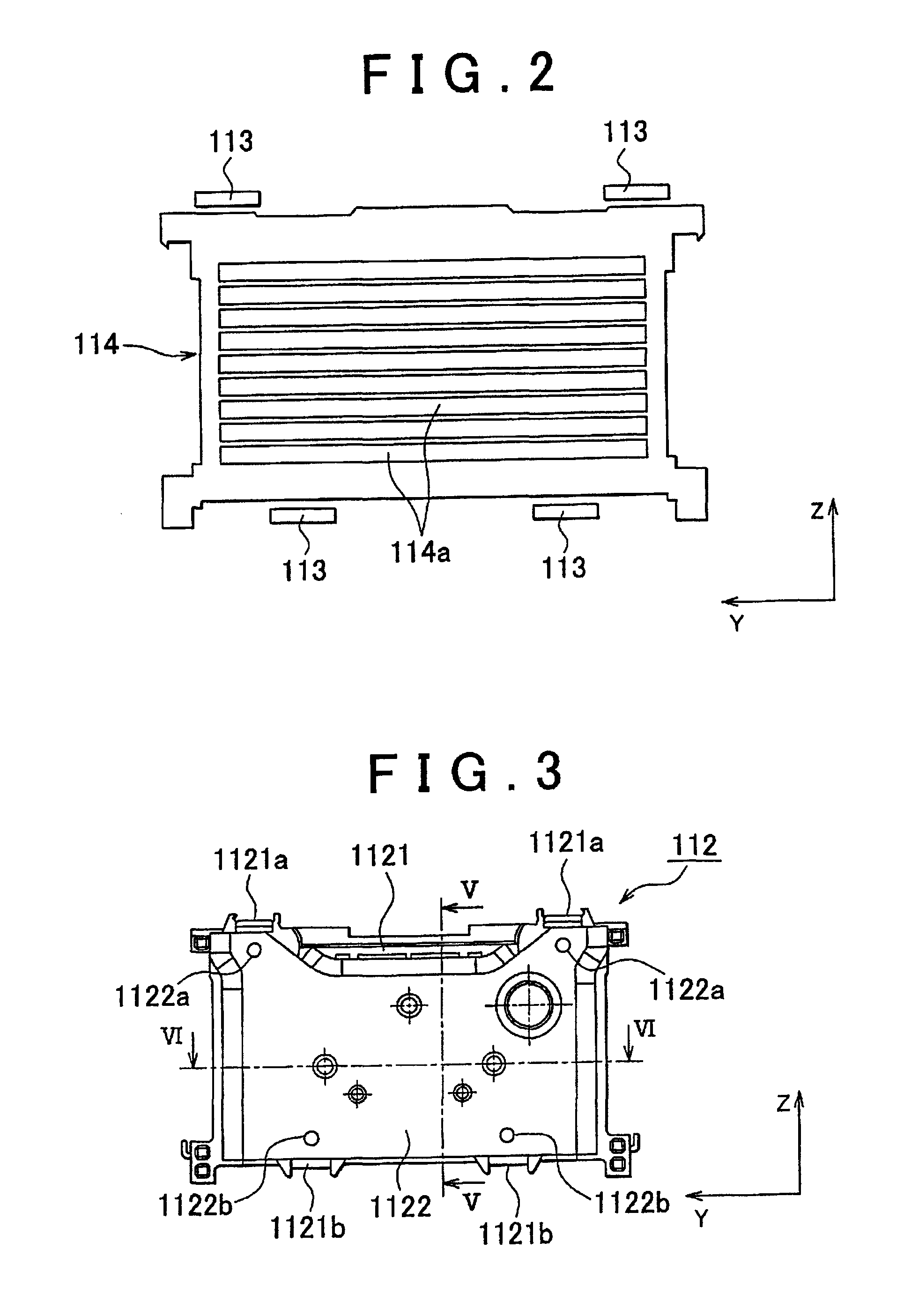

Image

  • Electricity storage device
  • Electricity storage device
  • Electricity storage device

Examples


Embodiment Construction

[0020]An embodiment of the invention will be described below.

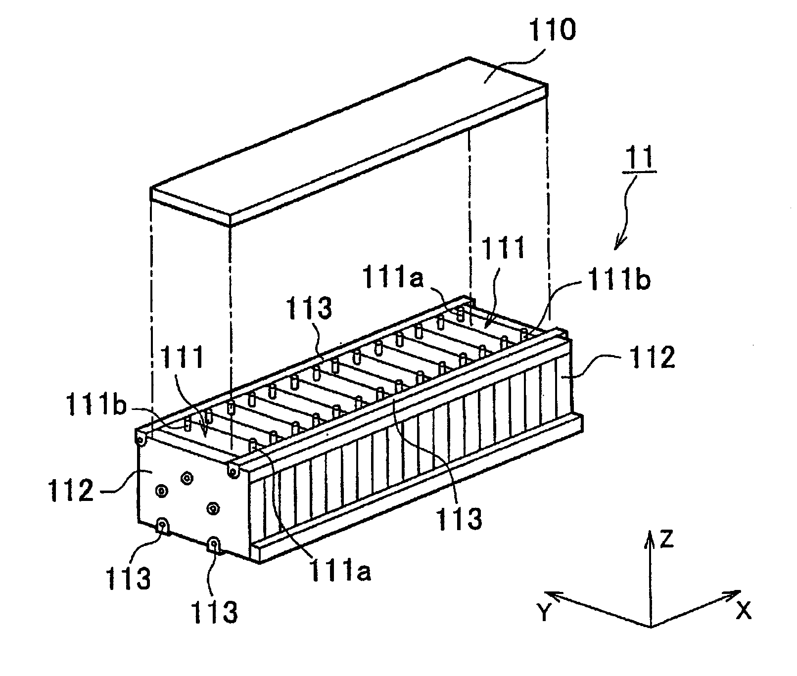
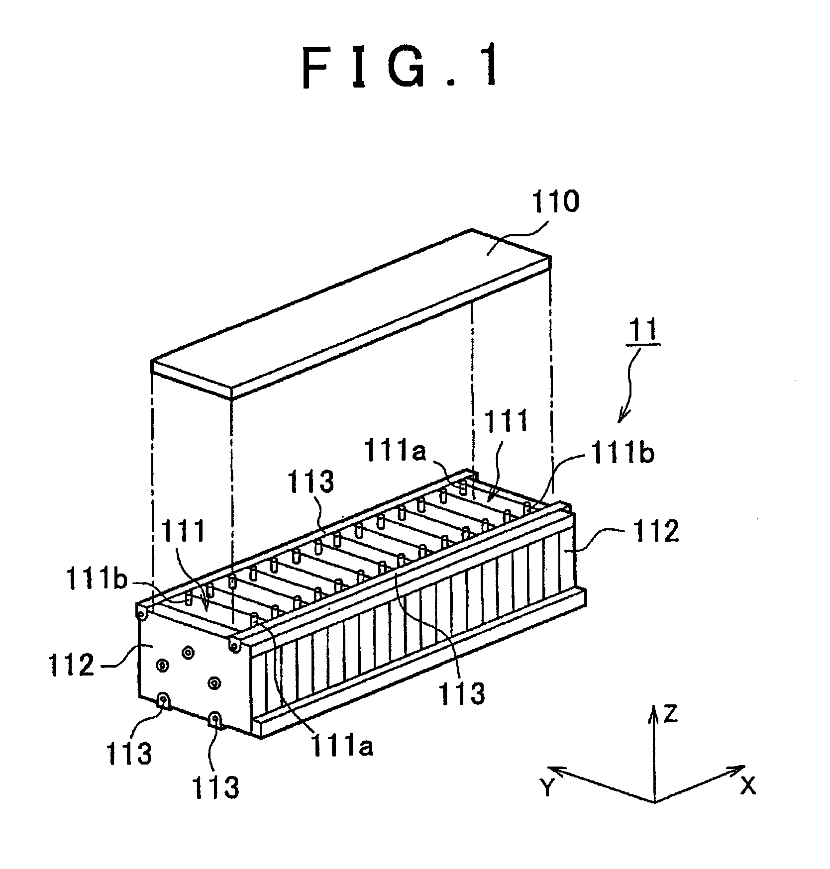
[0021]A battery pack, serving as an electricity storage device, that is an embodiment of the invention will be described with reference to FIG. 1. FIG. 1 is an external view of the battery pack and the X, Y, and Z axes shown in FIG. 1 are orthogonal to each other.

[0022]The battery pack 11 of this embodiment can be mounted on a vehicle and examples of the vehicle include hybrid vehicles and pure electric vehicles. The hybrid vehicle is a vehicle equipped with an internal combustion engine or a fuel cell in addition to the battery pack 11 as the motive power source for driving the vehicle. The pure electric vehicle is a vehicle equipped with the battery pack 11 alone as the motive power source of the vehicle.

[0023]The battery pack 11 may be connected to a motor / generator (not shown), which receives the output from the battery pack 11 to generate the kinetic energy for driving the vehicle. The torque output from the motor / gen...


PUM


Abstract

An electricity storage device includes: a plurality of cells that are aligned in a predetermined direction; a pair of end plates that sandwich the plurality of cells in the predetermined direction; and a restraining member that extends in the predetermined direction, is fixed to the pair of end plates, and exerts a restraining force on the plurality of cells in the predetermined direction via the end plates. Each of the end plates includes a first plate and a second plate. The first plate has a plurality of ribs on a surface that faces the adjacent cell and is formed of insulating material. The second plate is fixed to the first plate on a side opposite to the surface that faces the adjacent cell and is formed of material stronger than the insulating material for the first plate.

Description

BACKGROUND OF THE INVENTION[0001]1. Field of the Invention[0002]The invention relates to an electricity storage device that exerts a restraining force on a plurality of cells with the use of end plates.[0003]2. Description of Related Art[0004]In some cases, a plurality of unit cells are aligned in a direction when the plurality of unit cells are used to form a battery pack. A pair of end plates are placed at two ends in the direction of alignment of the unit cells and the end plates are used to exert a restraining force on the plurality of unit cells (see Japanese Patent Application Publication No. 2006-253149 (JP-A-2006-253149), for example).[0005]In the case of a structure, in which the end plates are in contact with the unit cells, however, there is a fear that the temperature of the unit cells that are in contact with the end plates becomes lower than the temperature of the other unit cells that are not in contact with the end plates because the heat of the unit cells is transfe...

Claims


Application Information

Patent Timeline
IPC IPC(8): H01M2/10H01M10/50H01M10/613H01G2/08H01G11/10H01G11/12H01G11/18H01G11/78H01M10/60H01M10/615H01M10/617H01M10/625H01M10/647H01M10/6557H01M10/6561H01M10/658H01M50/209H01M50/224H01M50/227H01M50/264H01M50/291
CPCH01M2/1077H01M6/42H01M10/0413H01M10/0472H01M10/0481H01M10/5006H01M10/5075H01M10/5016H01M10/5055H01M10/5059H01M10/5032H01M2/1061H01M10/5008H01M10/625H01M10/615H01M10/647H01M10/6557H01M10/6567H01M10/6555H01M10/617Y02E60/10Y02P70/50H01M50/209H01M50/224H01M50/264H01M50/291H01M50/227
Inventor OSAKABE, TOMOTAKAWAKASUGI, MIKIOIMAI, MASAHIROMURAYAMA, RYOGO
Owner TOYOTA JIDOSHA KK
Learn More