
Chemiluminescence compact imaging scanner

a compact imaging and chemiluminescence technology, applied in the field of molecular biology and microbiology, can solve the problem that each sweep or pass might take a few minutes, and achieve the effect of facilitating image registration and reconstruction

Active Publication Date: 2013-06-20
LI COR
View PDF23 Cites 15 Cited by
  • Summary
  • Abstract
  • Description
  • Claims
  • Application Information

AI Technical Summary

Benefits of technology

This patent describes a new technology that allows for more efficient and accurate imaging of samples. By scanning the sample closely, instead of using wide area imagers, researchers can collect more light from dim luminescence. Additionally, by using high NA optics and large effective pixel sizes, researchers can maximize the amount of photons collected. This technology also avoids distortion artifacts that can occur with wider area imagers and produces images of all wells in the same manner with minimal distortion. Overall, this technology improves the accuracy and efficiency of biological research.

Problems solved by technology

Because of the extremely low light from chemiluminescence and commensurate dearth of photons for the CCD to pick up, each sweep or pass might take a few minutes.

Method used


Image

  • Chemiluminescence compact imaging scanner
  • Chemiluminescence compact imaging scanner
  • Chemiluminescence compact imaging scanner

Examples


Embodiment Construction

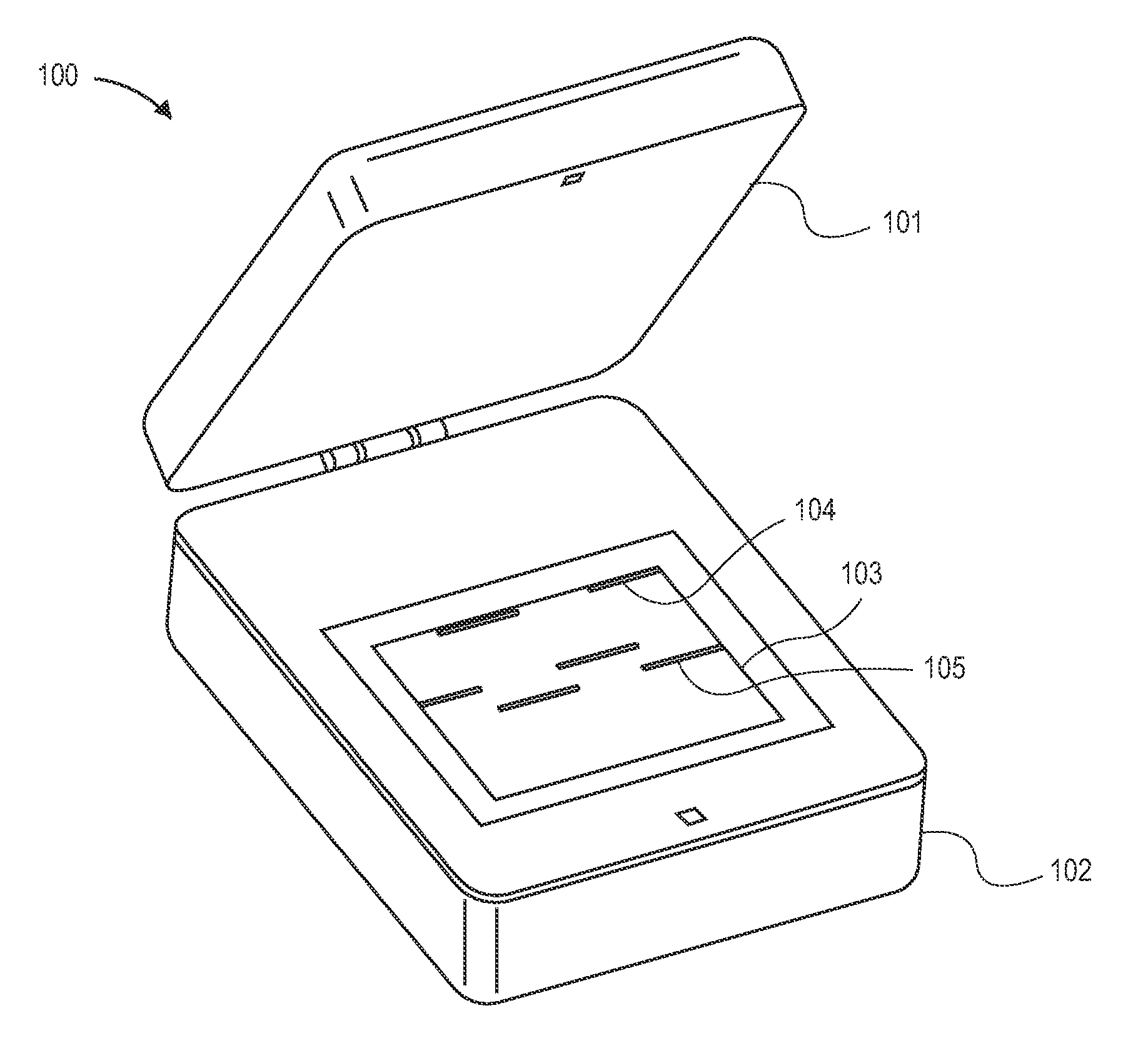
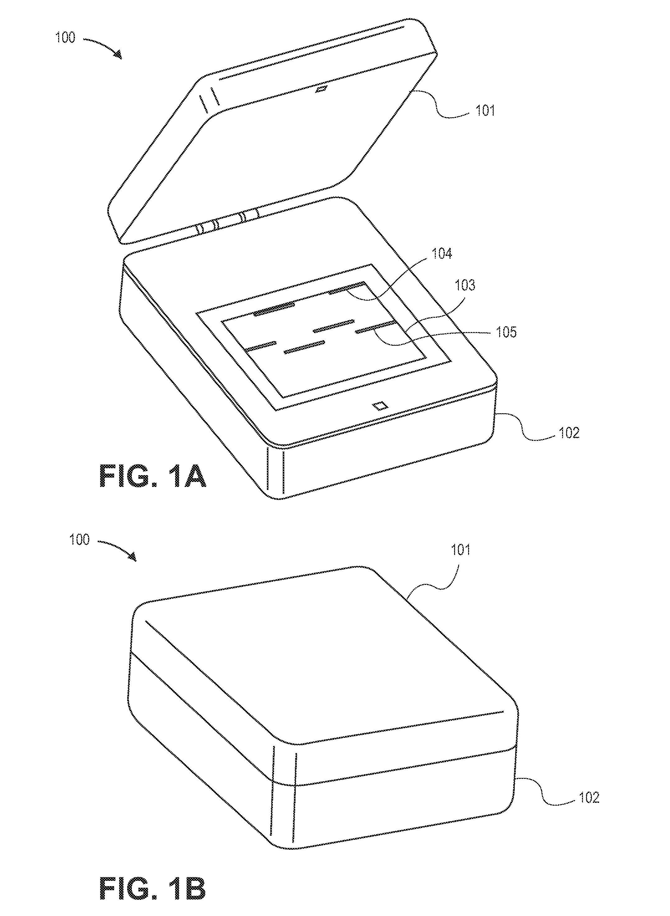
[0040]Presented herein is a novel imaging method and apparatus that achieves the sensitivity of high-end CCD imagers but with a significantly smaller size and without the need for cooling. The imaging apparatus can therefore be produced and maintained at a much lower cost than before.

[0041]In chemiluminescence imagers of the prior art, the choice of the CCD, its packaging, and its electronics are often primarily driven by the need for low total noise. This typically requires the use of high-end, scientific CCDs. These scientific CCDs are typically small in size, in the range of 1 centimeter (cm)×1 cm. The size of a typical Western Blot is on the order of 10 cm×10 cm. Thus, low NA lenses and other imaging optics are needed to project the sample area onto to the smaller CCD area at the appropriate focal lengths. Such imaging requires a total optical path of hundreds of millimeters (mm), which results in a physically large imager.

[0042]The larger the sample, the longer the working dist...


PUM

PropertyMeasurementUnit
Temperatureaaaaaaaaaa
Lengthaaaaaaaaaa
Lengthaaaaaaaaaa

Abstract

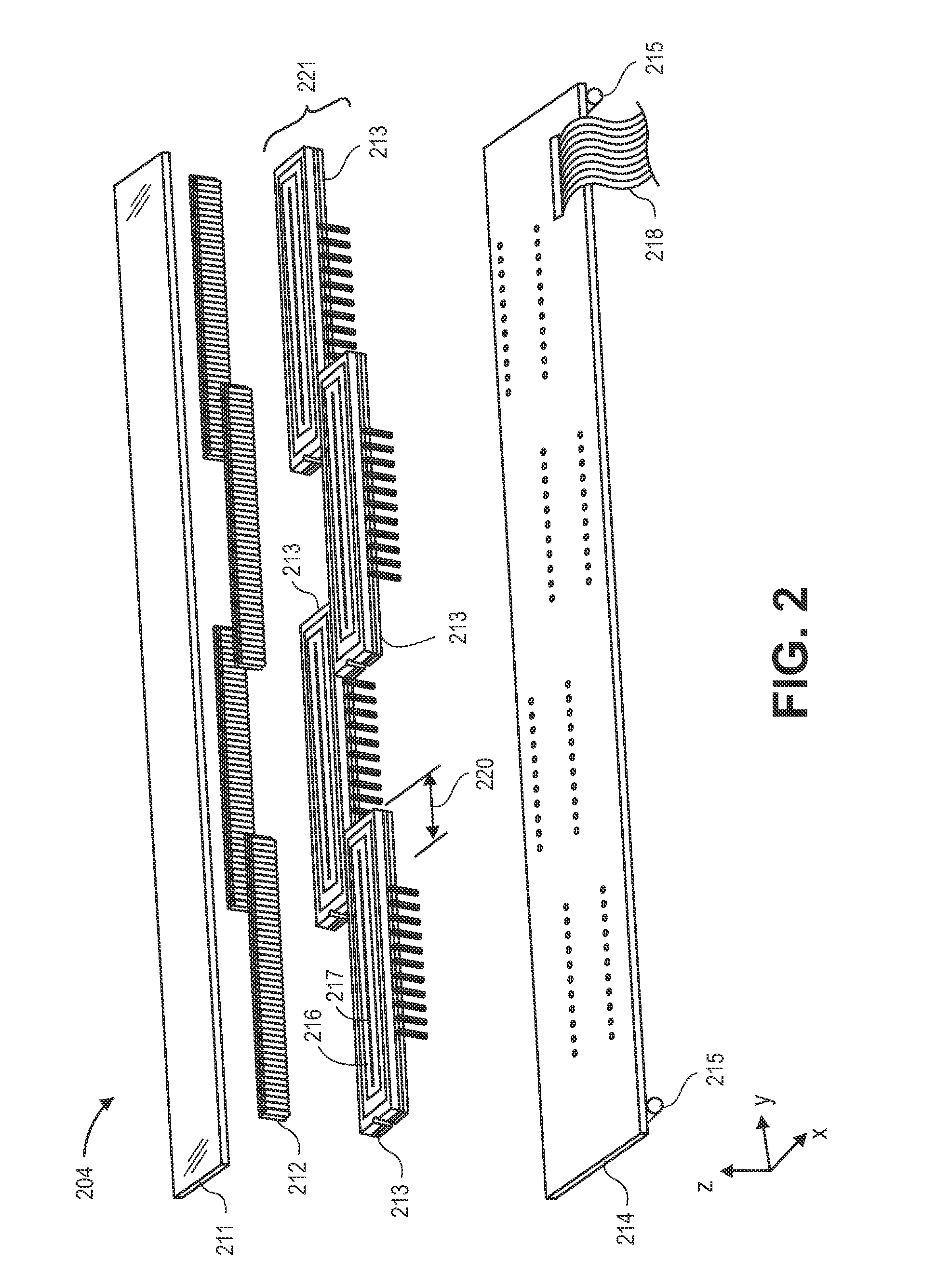
Systems, devices, and methods for accurately imaging chemiluminescence and other luminescence are disclosed. A compact, flat-bed scanner having a light-tight enclosure, one or more detector bars of linear charge-coupled device (CCD) or complementary metal oxide semiconductor (CMOS) imaging chips, and high working numerical aperture (NA) optics scans closely over a sample in one direction and then the opposite direction. Averages or other combinations of intensity readings for each pixel location (x, y) between the two or more passes are averaged together in order to compensate for luminescence that varies over time. On-chip pixel binning and multiple clock frequencies can be used to maximize the signal to noise ratio in a CCD-based scanner.

Description

CROSS-REFERENCES TO RELATED APPLICATIONS[0001]This application claims the benefit of U.S. Provisional Patent Application No. 61 / 576,941, filed Dec. 16, 2011, the contents of which are hereby incorporated by reference in its entirety for all purposes.STATEMENT AS TO RIGHTS TO INVENTIONS MADE UNDER FEDERALLY SPONSORED RESEARCH OR DEVELOPMENT[0002]NOT APPLICABLECOPYRIGHT NOTICE[0003]A portion of the disclosure of this patent document contains material which is subject to copyright protection. The copyright owner has no objection to the facsimile reproduction by anyone of the patent document or the patent disclosure, as it appears in the Patent and Trademark Office patent file or records, but otherwise reserves all copyright rights whatsoever.BACKGROUND[0004]1. Field of the Invention[0005]Generally, this application relates to molecular biology and microbiology chemistry processes and apparatuses including optical measuring or testing means. Certain embodiments relate to devices, system...

Claims


Application Information

Patent Timeline
IPC IPC(8): G01N33/53G01N21/64G01N27/447C12M1/34
CPCG01N21/76G01N21/6486H04N1/1017H04N1/1933C12Q1/6825H04N1/191G01N33/54373G01J1/0403G01N33/53G01N33/5302G01N21/62
Inventor BOUZID, AHMEDLESIAK, CHRISKONZ, DANIEL W.FRANZEN, DAVID L.BIGGS, WILLIAMANDERSON, JON P.
Owner LI COR
Learn More