Thrombus removal apparatus and method

a technology of thrombosis and thrombosis, which is applied in the field of thrombosis removal apparatus and to a method, can solve the problems of lengthening the time required to break down the thrombosis

Active Publication Date: 2013-06-20
COOK MEDICAL TECH LLC
View PDF14 Cites 27 Cited by
  • Summary
  • Abstract
  • Description
  • Claims
  • Application Information

AI Technical Summary

Benefits of technology

[0007]Conventional thrombus removal apparatus generally seeks to isolate the area of the thrombus prior to the administration of a thrombolytic agent, in order to prevent the seepage or transfer of the thrombolytic agent to other parts of the patient's system, in particular to the whole of the patient's bloodstream. Isolation can be achieved by a double balloon arrangement in which the balloons are positioned either side of a thrombus to be treated and inflated to close off that part of the patient's lumen. Such isolation prevents undesired effects on the patient and allows for the use of more concentrated doses of thrombolytic agent. However, the inventors have found that isolating a thrombus in this manner causes stagnation of blood in the isolated region, which can cause a lengthening of the time required to breakdown the thrombus. By contrast, the apparatus taught herein does not entirely isolate the thrombus from the patient's bloodstream as the space proximal of the occlusion device remains open to the patient's bloodstream, such that there will continue to be some movement, or turbulence, of blood around the thrombus caused by the natural pumping and movement of the patient's circulatory system. This can assist in speeding up the breakage of thrombus material, particularly when this is well established. Thus, the structure taught herein could be said to occlude the vessel one side (preferably downstream) of the thrombus and to leave the other side (preferably upstream) exposed to the patient's blood stream.
[0008]Furthermore, the apparatus taught herein can act to scrape a thrombus from a vessel wall, which again can speed up the process of removal of the thrombus. A combination of thrombolytic agent administered with the taught apparatus and scraping of the thrombus can lead to much faster removal of a thrombus than with prior art devices.
[0017]When inflated, a radius of the balloon can taper, in preferably a linear fashion, from a radially outermost section to the first and second ends of the balloon. Such a shape provides an improved scraping effect as it provides an effectively pointed cross-section.
[0018]Additionally, the radially outermost section of the balloon may be provided with a circumferential flange to act as a scraper along the walls of a vessel. This can provide a particularly effective scraping action analogous to a windscreen wiper.

Problems solved by technology

However, the inventors have found that isolating a thrombus in this manner causes stagnation of blood in the isolated region, which can cause a lengthening of the time required to breakdown the thrombus.

Method used


Image

  • Thrombus removal apparatus and method
  • Thrombus removal apparatus and method
  • Thrombus removal apparatus and method

Examples


Embodiment Construction

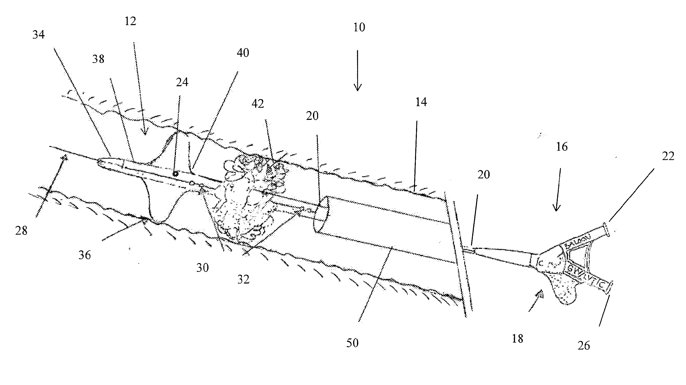
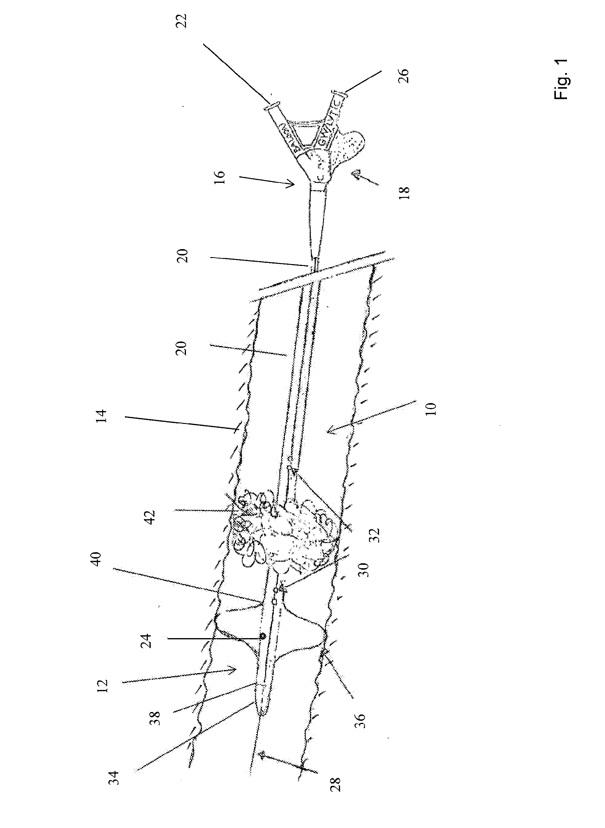
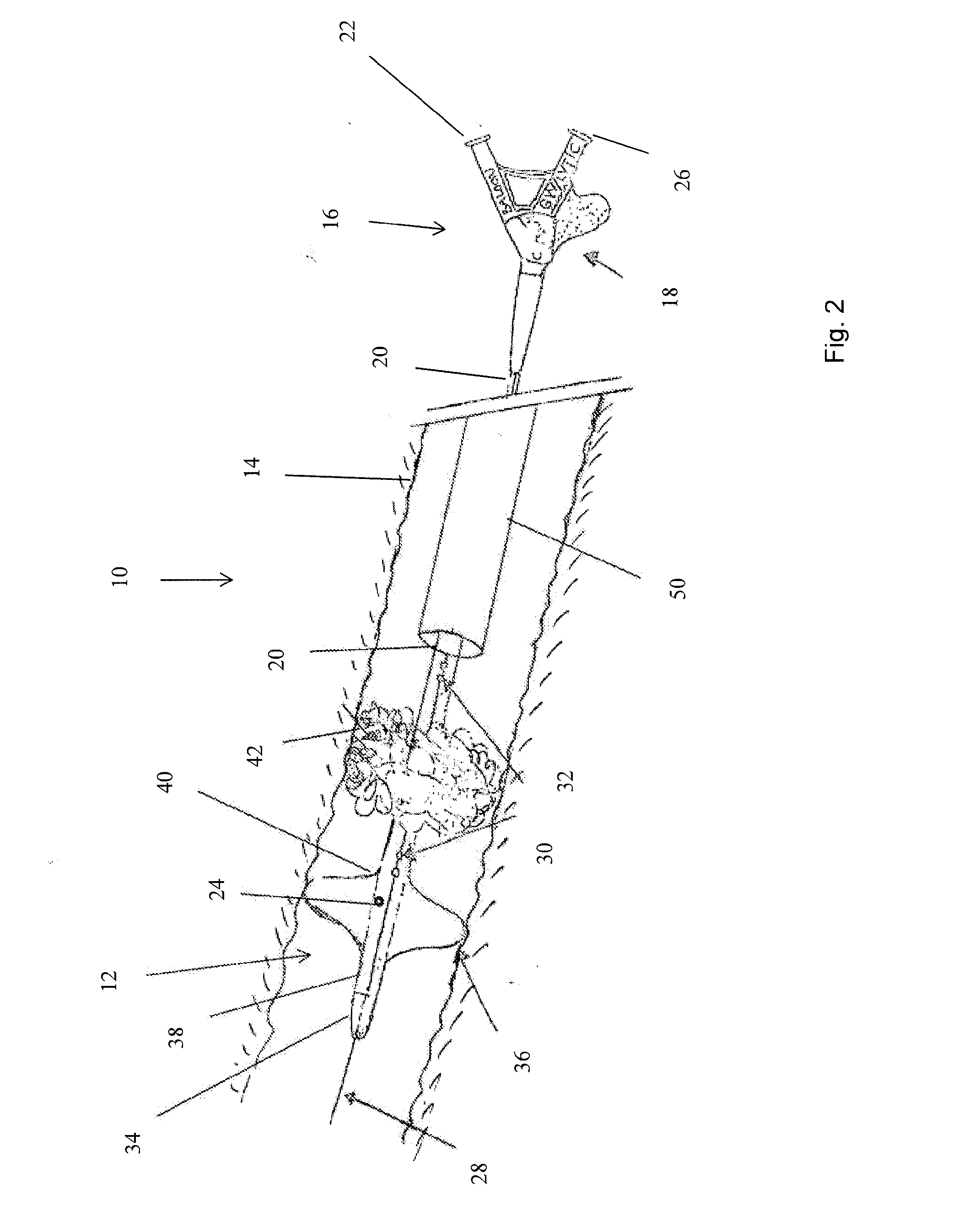
[0049]There are shown in the accompanying drawings preferred embodiments of thrombus treatment apparatus. It will be appreciated that only the principal components of the apparatus are shown in the drawings and described below and that other components of the apparatus will be well known to the person skilled in the art and are therefore not described herein in any detail. The assembly will particularly include, thus, the components of a standard introducer assembly such as a guide wire, a carrier sheath, an external manipulation unit coupled to the carrier sheath and having one or more haemostatic valves as well as couplings for flushing fluid and the like. The components will typically include those used for the commonly performed Seldinger technique for introducing the thrombus removal apparatus percutaneously into the patient.

[0050]It will also be understood that the features depicted in the drawings are not necessarily to scale and have been drawn preliminary with clarity of di...


PUM


Abstract

Thrombus removal apparatus includes a balloon catheter with a short balloon at a distal end thereof. An aspiration catheter is disposed coaxially over the balloon catheter. The balloon catheter includes a plurality of holes for the administration of lytic agent. The apparatus does not seal off completely the zone of the vessel around the thrombus, thereby allowing movement of blood within the vessel. The balloon is shaped so that it can be pulled along the vessel in an upstream direction so as to drag against the vessel walls for assisting in the removal of the thrombus.

Description

CROSS-REFERENCE TO RELATED APPLICATIONS[0001]This application is related to and claims the benefit of priority to GB 1121788.2, filed on Dec. 19, 2012 which is incorporated herein by reference in its entirety.TECHNICAL FIELD[0002]The present invention relates to thrombus removal apparatus and to a method of removing a thrombus from a patient.BACKGROUND ART[0003]There are established procedures for removing thrombi from a patient's vasculature by percutaneous insertion of appropriate treatment apparatus into the vasculature of the patient. A procedure which is well documented involves the use of an assembly which includes a balloon catheter provided with two inflatable balloons which are spaced from one another at the distal end of the catheter. The balloon catheter is inserted endoluminally into the patient's vasculature until the balloons are located either side of a thrombus to be removed. The balloons are then inflated so as to close off that part of the patient's vessel. The ass...

Claims


Application Information

Patent Timeline
Patent Type & Authority Applications(United States)
IPC IPC(8): A61M25/10A61B17/3207
CPCA61B17/3207A61M25/104A61M25/1002A61M2025/1052A61M2025/109A61B2017/22084A61B17/320725A61B2017/22061A61B2017/22067A61B2017/22079A61B17/22A61B17/22032A61M25/0067A61M25/10
Inventor AGGERHOLM, STEENOLSEN, KIAN
Owner COOK MEDICAL TECH LLC
Why Eureka
Try Eureka