Hydraulic shovel positional guidance system and method of controlling same

a positional guidance system and hydraulic shovel technology, applied in the direction of distance measurement, navigation instruments, instruments, etc., can solve the problems of not being able to accurately determine whether the hydraulic shovel is in not being able to move the hydraulic shovel to a suitable position for performing work, and not being able to achieve the ground within the work area

Inactive Publication Date: 2013-06-20
KOMATSU LTD
View PDF0 Cites 39 Cited by
  • Summary
  • Abstract
  • Description
  • Claims
  • Application Information

AI Technical Summary

Benefits of technology

[0026]In the hydraulic shovel positional guidance system according to the tenth aspect of the present invention, the position of the main vehicle body where the diggable range, in which the target surface and the operability range overlap, is largest is calculated as the optimal work position. The guidance picture showing the optimal work position is then displayed on the display unit. Accordingly, an operator can easily move the hydraulic shovel to a position suitable for performing work by moving the hydraulic shovel towards the optimal work position shown in the guidance picture.
[0027]In the hydraulic shovel positional guidance system according to the eleventh aspect of the present invention, the position of the main vehicle body where the diggable range, in which the target surface and the operability range overlap, is largest is calculated as the optimal work position. A guidance picture showing the optimal work position is then displayed on the display unit. Accordingly, an operator can easily move the hydraulic shovel to a position suitable for performing work by moving the hydraulic shovel towards the optimal work position shown in the guidance picture.

Problems solved by technology

However, it is not easy to accurately decide whether the hydraulic shovel is in a position suitable for performing work.
Additionally, it is not easy to move the hydraulic shovel to a position suitable for performing work even when referring to the positional relationship of the target surface and the range of motion of the tip of the bucket in the guidance picture.
The ground within the work area is not always flat, and is often rough.
It is therefore difficult to precisely calculate the optimal work position if the optimal work position is calculated based on the height of the operability range at the current position of the main vehicle body.

Method used


Image

  • Hydraulic shovel positional guidance system and method of controlling same
  • Hydraulic shovel positional guidance system and method of controlling same
  • Hydraulic shovel positional guidance system and method of controlling same

Examples


Embodiment Construction

1. Configuration

1-1. Overall Configuration of Hydraulic Shovel

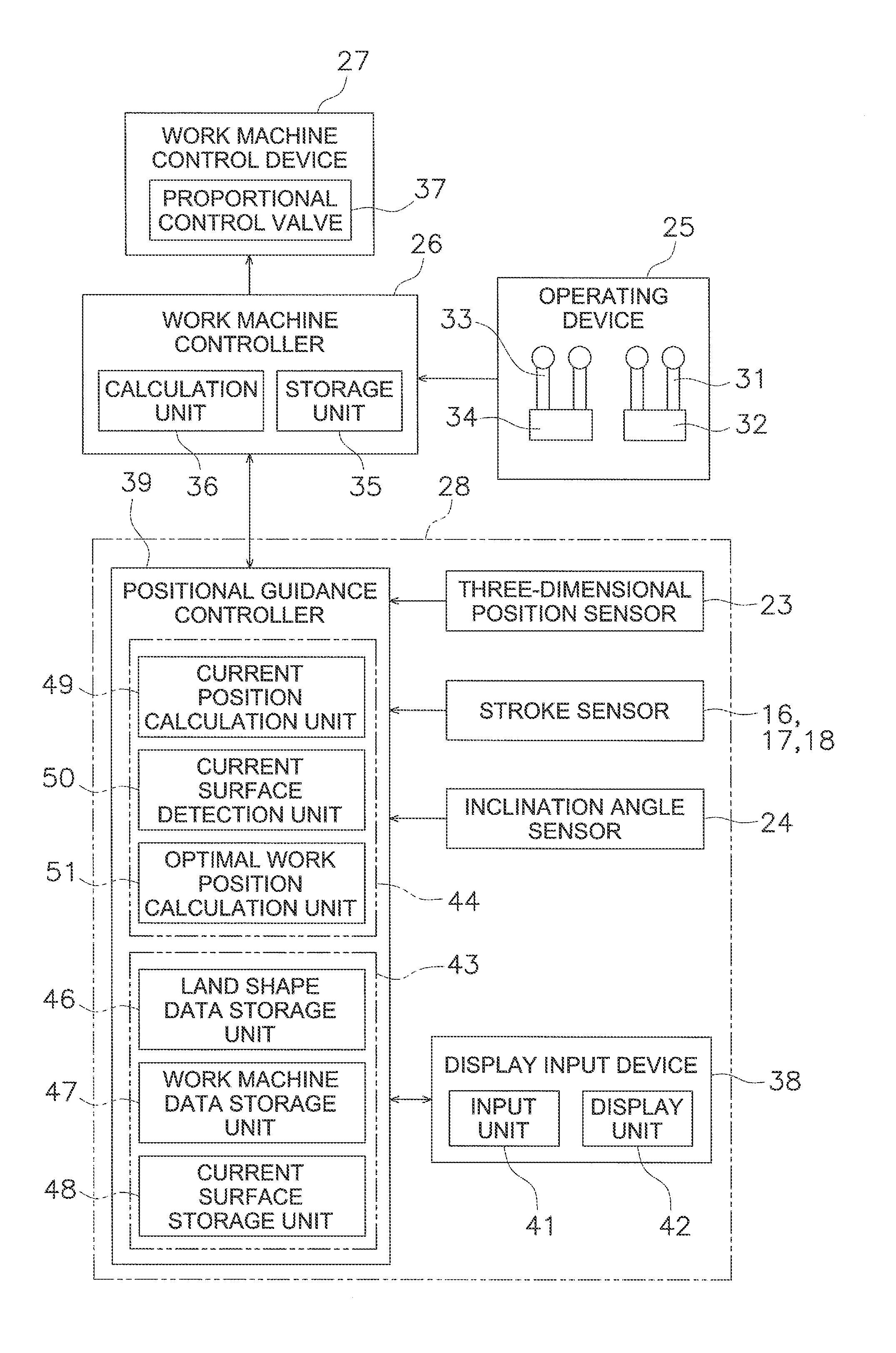
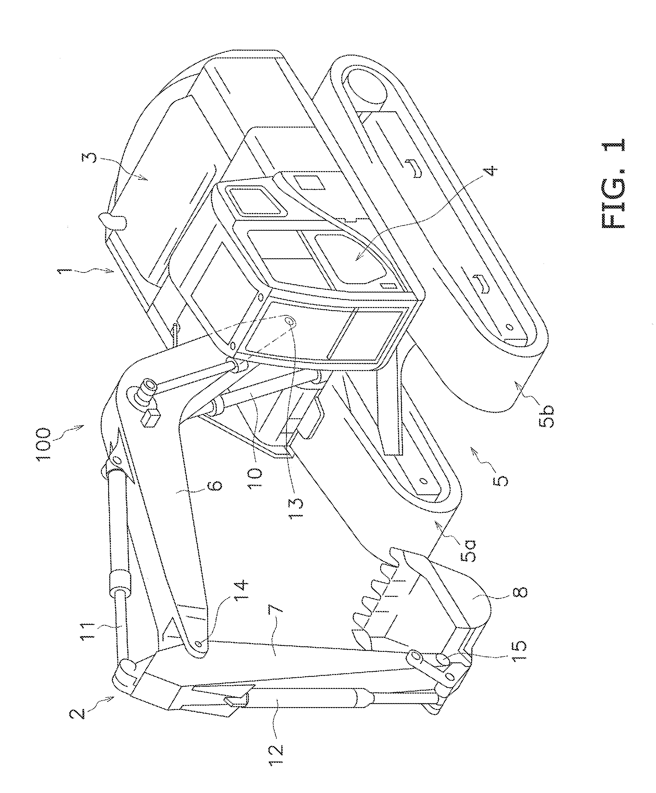
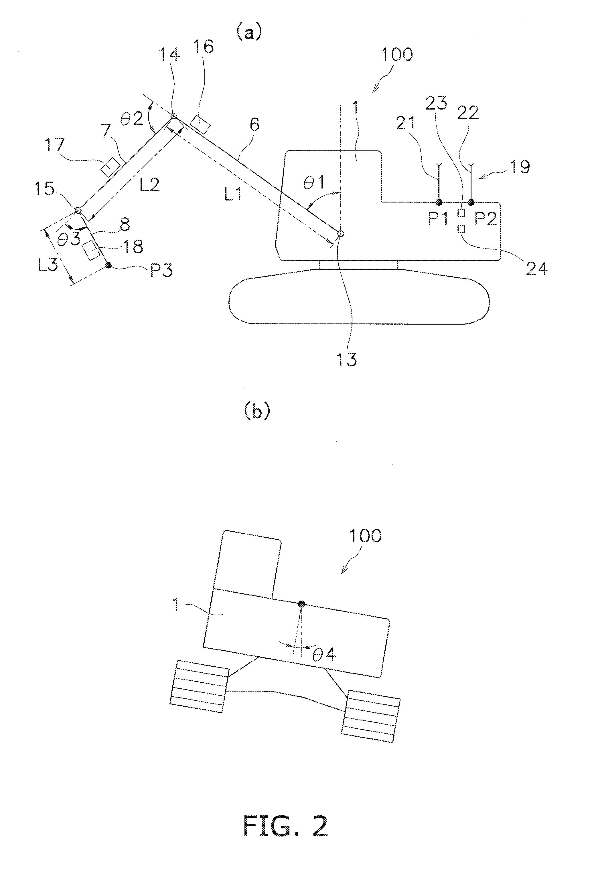
[0044]There follows a description of a hydraulic shovel positional guidance system according to an embodiment of the present invention with reference to the drawings. FIG. 1 is a perspective view of a hydraulic shovel 100 in which a positional guidance system is installed. The hydraulic shovel 100 has a main vehicle body 1 and a work machine 2. The main vehicle body 1 has an upper pivoting body 3, a cab 4, and a travel unit 5. The upper pivoting body 3 includes devices, such as an engine, a hydraulic pump, and / or the like, which are not shown in the drawings. The cab 4 is installed on the front of the upper pivoting body 3. A display input device 38 and an operating device 25 described below are disposed within the cab 4 (cf. FIG. 3). The travel unit 5 has tracks 5a, 5b, and the rotation of the tracks 5a, 5b causes the hydraulic shovel 100 to travel.

[0045]The work machine 2 is attached to the front of the main vehicle bod...


PUM


Abstract

In a hydraulic shovel positional guidance system, an optimal work position calculation unit is configured to calculate an optimal work position of a main vehicle body where a diggable range in which a target surface and an operability range overlap is largest. A display unit is configured to display a guidance picture showing the optimal work position.

Description

CROSS-REFERENCE TO RELATED APPLICATIONS[0001]This application claims priority to Japanese Patent Application No. 2011-036200 filed on Feb. 22, 2011, the disclosure of which is hereby incorporated herein by reference in its entirety.TECHNICAL FIELD[0002]The present invention relates to a hydraulic shovel positional guidance system and a method for controlling same.BACKGROUND ART[0003]A positional guidance system for guiding a hydraulic shovel or other work vehicle to a target work object is known. For example, the positional guidance system disclosed in Japanese Laid-open Patent Application Publication 2001-98585 has design data showing a three-dimensional design land shape. The design land shape comprises a plurality of design surfaces, and part of the design surfaces is selected as a target surface. The current position of the hydraulic shovel is detected using position measuring means such as a GPS. The positional guidance system displays a guidance picture showing the current pos...

Claims


Application Information

Patent Timeline
Patent Type & Authority Applications(United States)
IPC IPC(8): E02F9/26
CPCE02F9/261E02F9/26E02F9/264E02F3/43E02F9/20G01C15/00
Inventor FUKANO, RYOFUJITA, ETSUOANDO, MASAO
Owner KOMATSU LTD
Why Eureka
Try Eureka