Double clutch transmission having a layshaft design

a transmission and clutch technology, applied in mechanical equipment, transportation and packaging, gearboxes, etc., can solve the problems of insufficient radial construction space in various vehicle systems, drive motors, in particular internal combustion engines, and insufficient radial construction space for large-radial space. achieve the effect of good power-shiftability and low overall

Inactive Publication Date: 2013-06-27
ZF FRIEDRICHSHAFEN AG
View PDF6 Cites 3 Cited by
  • Summary
  • Abstract
  • Description
  • Claims
  • Application Information

AI Technical Summary

Benefits of technology

The double clutch transmission described in this patent has the ability to offer a wide range of gear ratios using a single countershaft and hollow shaft. This results in a compact and lightweight design that is efficient in its use of space. The transmission has good power-shift ability and can be combined with an electric machine easily. Its use of multiple shift devices further reduces the cost of production. Overall, the double clutch transmission has improved performance and versatility compared to traditional transmissions.

Problems solved by technology

However, only seven transmission ratios for forward travel can be implemented using the two double clutch transmissions described above, thereby preventing drive motors, in particular internal combustion engines, that can be coupled to the double clutch transmissions, from being operated to the desired extent in the optimum operating range thereof in respect, in particular, to the available tractive force and low fuel consumption, across a large operating range of the drive motors.
Since the double clutch transmission is designed with two countershafts, a larger radial construction space is required therefore, as compared to double clutch transmissions comprising one countershaft; the larger radial construction space is not available to the necessary extent in various vehicle systems.

Method used


Image

  • Double clutch transmission having a layshaft design
  • Double clutch transmission having a layshaft design
  • Double clutch transmission having a layshaft design

Examples


first embodiment

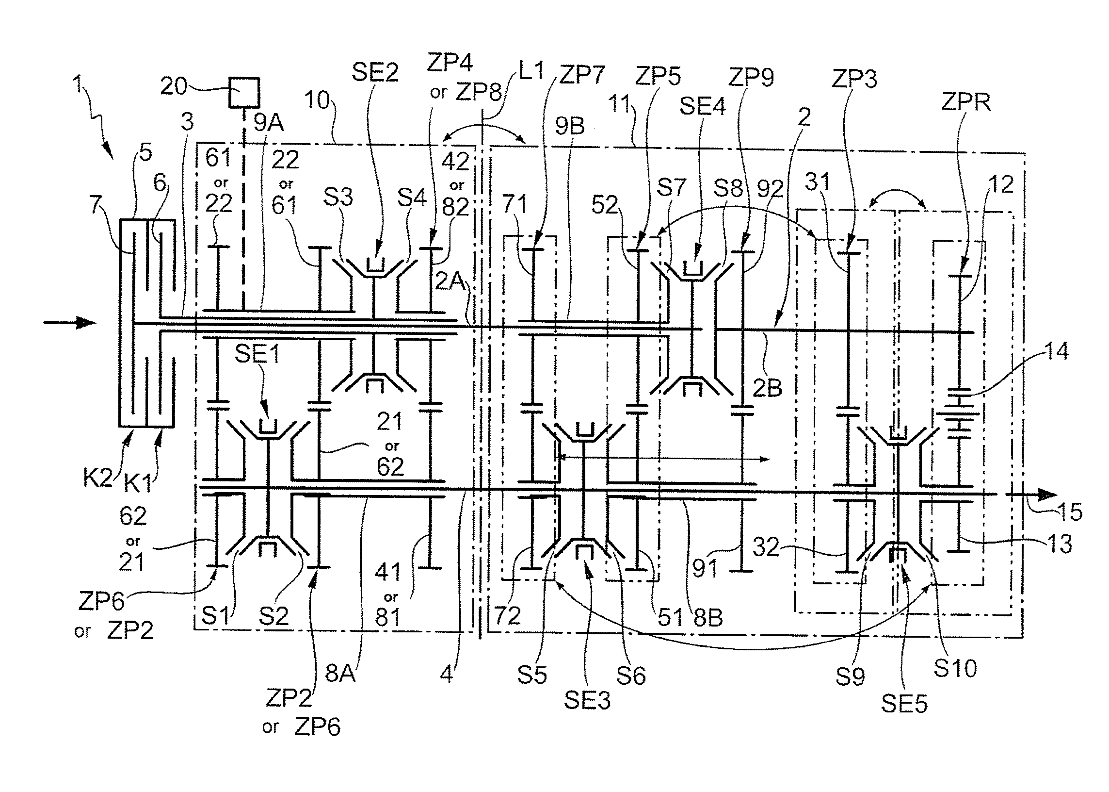
[0030]FIG. 1 shows two alternative example embodiments of a double clutch transmission 1 having a countershaft design; the example embodiments basically have the same design, and so the design of the double clutch transmission 1 will be described first by reference to the first embodiment, and then the differences between the two embodiments will be discussed in greater detail.

[0031]The double clutch transmission 1 comprises 17 gearwheels, one central transmission shaft 2 and a hollow transmission shaft disposed concentrically thereto, exactly one countershaft 4, and two power-shift elements K1, K2, which are embodied as friction-locking multi-disk clutches in the present case. The two power-shift elements K1 and K2 are the start-up elements of the double clutch transmission. In the installed state of the double clutch transmission, input elements, which are labeled “5”, of the power-shift elements K1, K2 are connected or operatively connected to a drive assembly, which is not shown...

second embodiment

[0048]In the aforementioned second embodiment of the double clutch transmission 1 according to FIG. 1, the two gear stages ZP2 and ZP6 are reversed in the axial extension of the central transmission shaft 2 relative to the above-described configuration in which the gear stage ZP6 is disposed between the gear stage ZP2 and the two power-shift elements K1, K2, and so the gear stage ZP2 is positioned between the gear stage ZP6 and the power-shift elements K1 and K2.

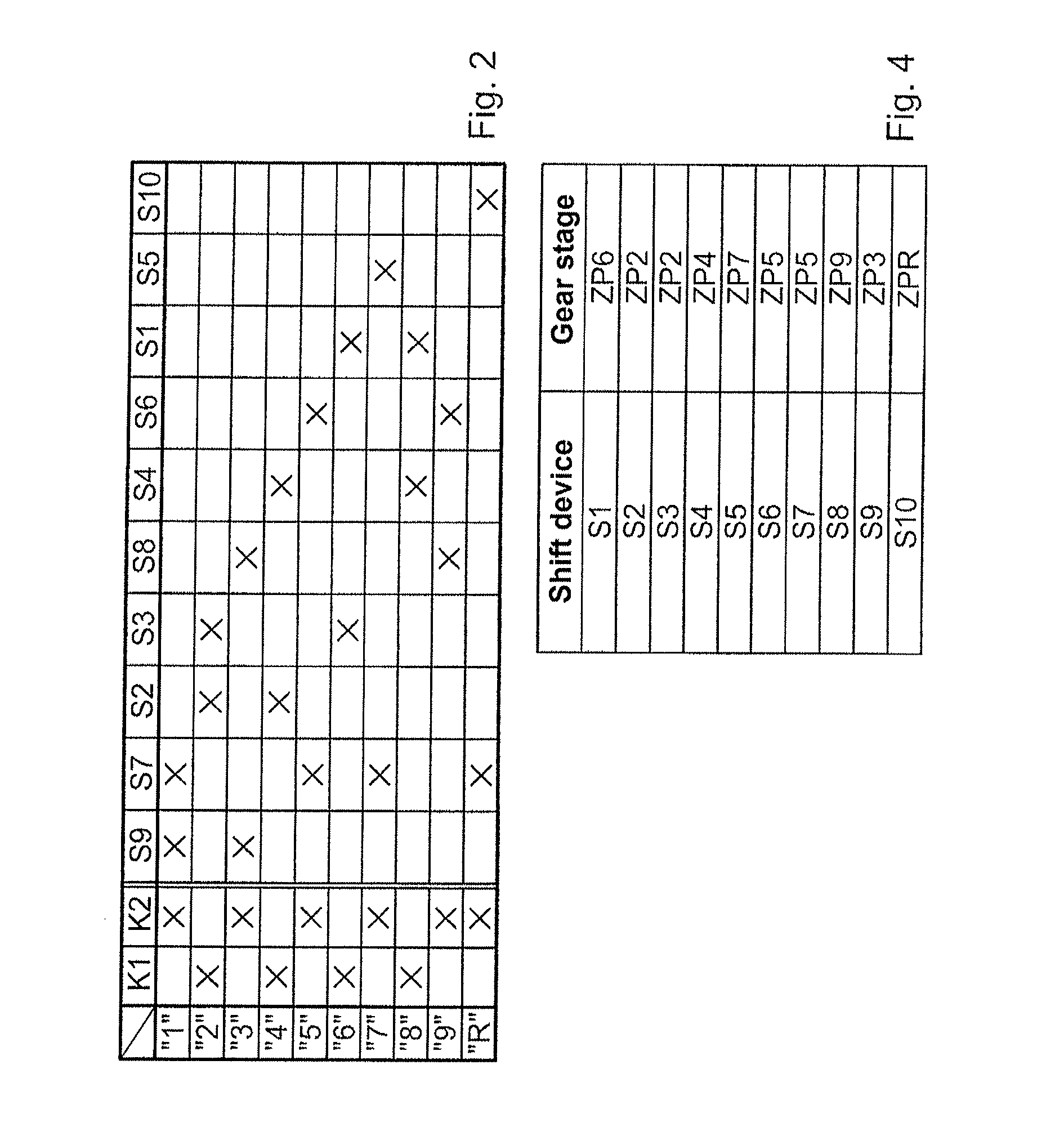
[0049]In the second embodiment of the double clutch transmission 1 according to FIG. 1, the shift elements S1 to S10 are actuated in a manner analogous to the shift logic depicted in greater detail in FIG. 3 in order to implement the transmission ratios “1” to “9” for forward travel and to implement the transmission ratio “R” for travel in reverse. Due to the reversed configuration of the gear stages ZP2 and ZP6, instead of the transmission ratio step “8”, the transmission ratio step “4”, in addition to the two other transmi...


PUM


Abstract

A double clutch transmission of countershaft design having a central shaft and a concentric hollow transmission shaft, one countershaft, and two power-shift elements. Two hollow shafts are disposed on the countershaft coaxially to the countershaft, each of which can be fixed, via one shift device, to the countershaft, and to which at least two gearwheels are fixed. A further hollow shaft is coaxially provided on either the central or hollow transmission shafts and can be connected, via a shift device, to the central or hollow transmission shaft, and to which at least two further gearwheels of the gear stages are fixed. At least three transmission ratios are possible by engaging three of the gear stages on the shift-element side into the power flow, thereby enabling one transmission ratio to be at least partially implemented by a respective sole engagement on the shift-element side into the power flow.

Description

[0001]This application is a National Stage completion of PCT / EP2011 / 063334 filed Aug. 3, 2011, which claims priority from German patent application serial no. 10 2010 040 660.0 filed Sep. 13, 2010.FIELD OF THE INVENTION[0002]The invention relates to a double clutch transmission having a countershaft design.BACKGROUND OF THE INVENTION[0003]A double clutch transmission having a countershaft design for implementing various transmission ratios for forward driving and travel in reverse, known from practical applications, is equipped with a central transmission shaft, a hollow transmission shaft disposed concentrically thereto, a countershaft, and two power-shift elements. Both of the power-shift elements are operatively connected on the input side to a drive assembly. One of the two power-shift elements is connected on the output side to the central transmission shaft, while the other of the two power-shift elements is connected on the output side to the hollow transmission shaft. The ce...

Claims


Application Information

Patent Timeline
Patent Type & Authority Applications(United States)
IPC IPC(8): F16H3/083
CPCB60K2006/4808B60K2006/4825B60K2006/4841F16H3/006F16H2003/0803Y10T74/19233F16H2200/006F16H2200/0065Y02T10/6252Y02T10/626F16H3/083F16H2003/0933Y02T10/62
Inventor DREIBHOLZ, RALFWAFZIG, JUERGENWECHS, MICHAELRENNINGER, MARKUSROSEMEIER, THOMASKALTENBACH, JOHANNESKAUFFELDT, RUDOLF
Owner ZF FRIEDRICHSHAFEN AG
Why Eureka
Try Eureka