
Virtual call center

a virtual call center and call center technology, applied in the computer field, can solve the problems of inefficient use of dedicated equipment infrastructure, limited capacity of dedicated equipment, and economic challenges of known outsourced call centers,

Active Publication Date: 2008-08-26
ALTO VENTURES INC
View PDF8 Cites 36 Cited by
  • Summary
  • Abstract
  • Description
  • Claims
  • Application Information

AI Technical Summary

Benefits of technology

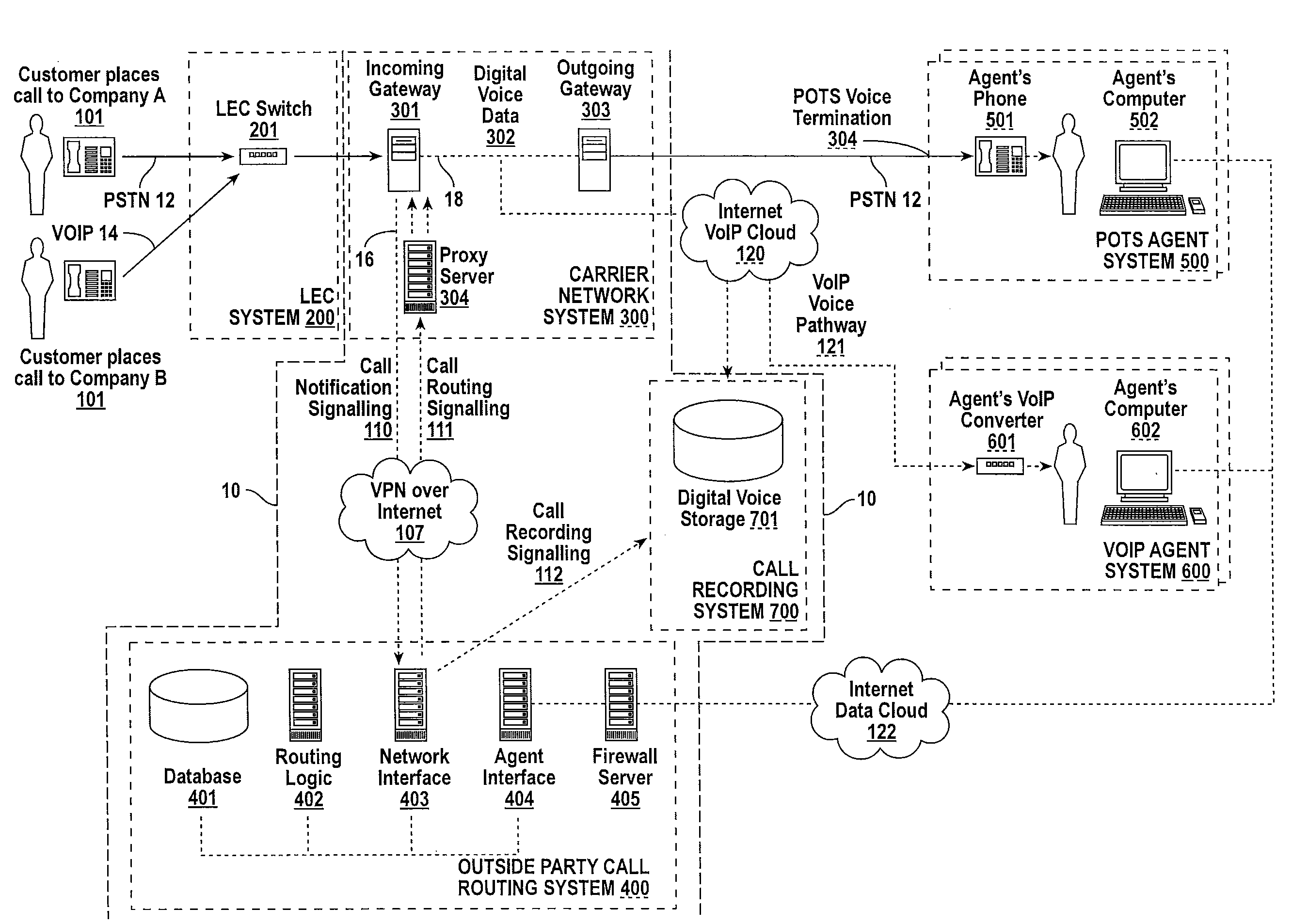
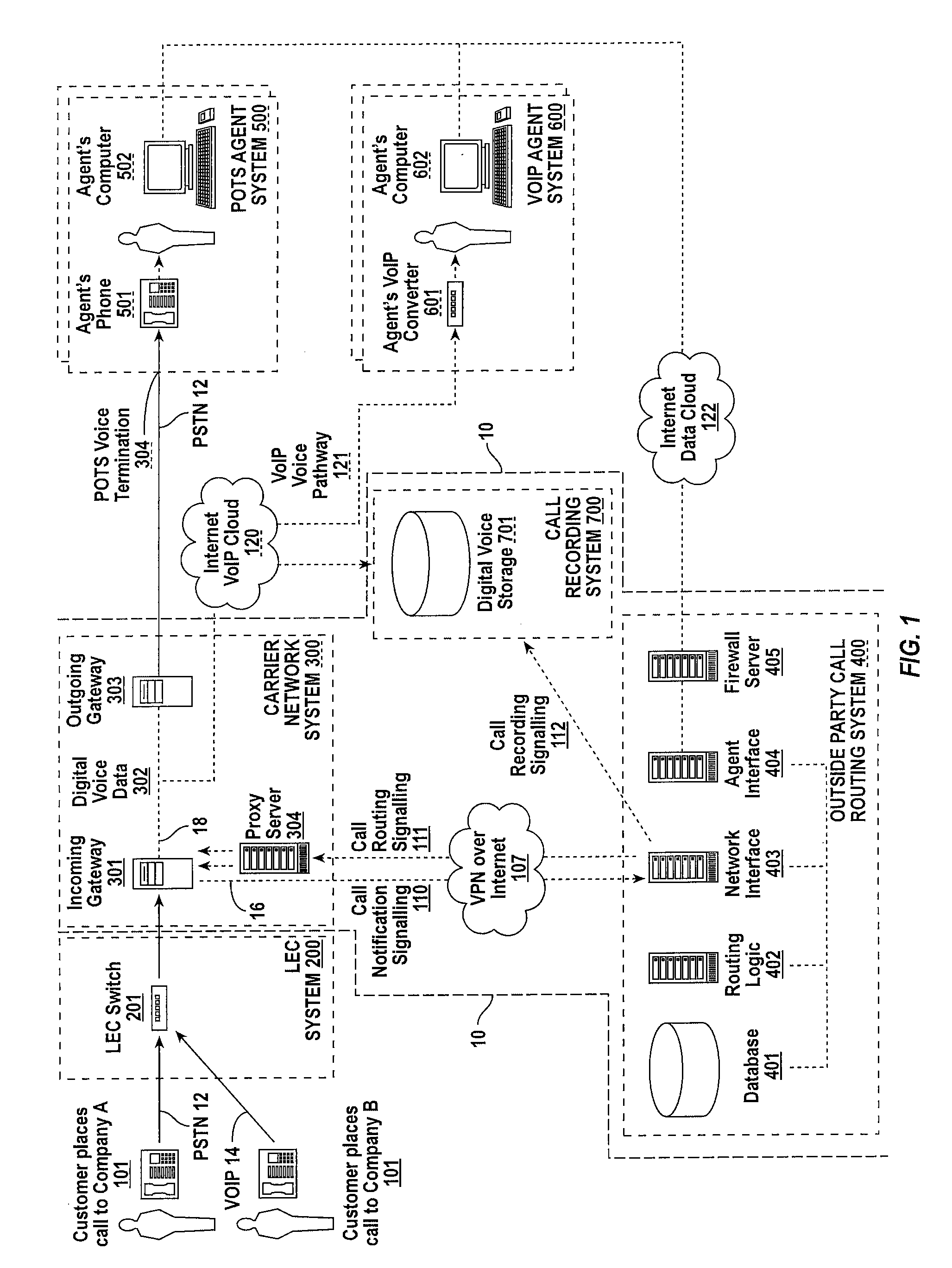
"The invention provides a system and methods for controlling calls in real-time without needing dedicated telecommunications equipment. The network carrier's equipment handles dynamic call routing, separating the call's signaling channel and bearer channel, allowing for control from outside of the carrier's network. The invention also provides a real-time signaling path and interface into the carrier network, allowing for routing decisions and business logic to remain outside of the carrier network while still carrying the voice channels."

Problems solved by technology

Known outsourced call centers have several limitations and economic challenges.
First, dedicated equipment can handle only a certain peak number of phone calls.
The difference between the average utilization rate and the peak demand levels can be very large, thus creating an economically inefficient use of the expensive dedicated equipment infrastructure.
Second, as a call center grows, it continually needs to expand its telecommunications infrastructure and the number of phone lines needed to handle the additional call load.
The capital outlay for fixed telecommunications equipment is often expensive, and the optimal growth of the telecommunications infrastructure equipment can be difficult to predict.
Third, if outsourced call centers use external agents physically outside of the company's premises, such as work-at-home phone agents or offshore phone agents, then the PBX or switched telecommunications solution is inherently inefficient: typically two legs (two circuits) of phone lines are required, the first being an incoming circuit used to deliver the incoming call to the PBX, the second being an outgoing circuit placed to connect from the PBX to the external agent.

Method used


Image

  • Virtual call center
  • Virtual call center
  • Virtual call center

Examples


Embodiment Construction

[0013]The program environment in which an embodiment of the invention is executed illustratively incorporates a general-purpose computer or a special purpose device such as a telephone gateway. Details of such devices (e.g., processor, memory, data storage, display) are well known and are omitted for the sake of brevity.

[0014]The techniques of the present invention may be implemented using a variety of technologies. For example, the methods described herein may be implemented in software executing on a computer system or implemented in hardware utilizing either a combination of microprocessors or other specially designed application specific integrated circuits (ASICs), programmable logic devices (PLDs), gate arrays or various combinations thereof. In particular, the methods described herein may be implemented by a sequence of computer-executable instructions transported by or residing on a medium, such as a carrier wave, disk drive, or computer-readable medium. Exemplary forms of c...


PUM


Abstract

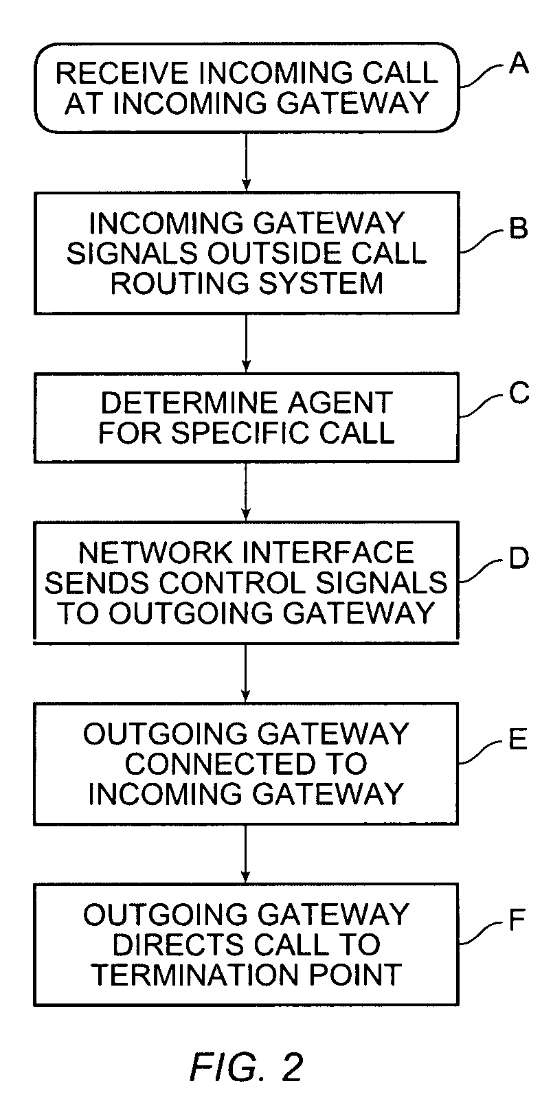
A system and methods are provided for enabling real-time call control. with minimal requirements for dedicated telecommunications PBX and dedicated switching equipment. Dynamic call routing is handled by a network carrier's equipment and an interface is provided at the carrier switch to dynamically redirect calls from outside of the carrier's network. A call's signaling channel and bearer (voice) channel are separated, allowing the voice carriage to continue to be handled by the network carrier, but the routing of the call is controlled from outside of the carrier's network. A real-time signaling path and interface is provided into the carrier network such that the associated routing decisions and business logic can remain outside of the carrier network, while the carrier network continues to carry the voice channels.

Description

BACKGROUND OF THE INVENTION[0001]This invention relates to the fields of computer and communications. More particularly, the invention relates to the dynamic routing and control of a voice telephone call in real-time.[0002]In a company call center setting, a PBX or other switching equipment is deployed to redirect incoming customer calls to the next available customer service agent to handle the incoming customer call. This in-house PBX or switch equipment is often coupled to dedicated incoming phone lines which serve only that particular company.[0003]In addition to routing an incoming call, an associated “screen-pop” is often presented on an agent's display in parallel with the incoming phone call. This “screen-pop” typically provides the phone agent with information associated with the customer.[0004]Outsourced call centers provide a more generalized solution whereby a telecommunications infrastructure is shared among many customers. Outsourced call centers are typically serviced...

Claims


Application Information

Patent Timeline
Patent Type & Authority Patents(United States)
IPC IPC(8): H04M3/00H04M3/42H04M5/00H04M7/00
CPCH04M3/5125H04M7/128H04M3/42221H04M3/5235H04M3/5183H04L12/4641
Inventor BROWN, WENDELL D.
Owner ALTO VENTURES INC
Learn More