Channel divider, sound reproducing system including the channel divider, and method for setting crossover frequency of the channel divider

a technology of channel divider and sound reproduction system, which is applied in the direction of transducer details, electrical transducers, electrical apparatus, etc., can solve the problems of difficult general users, difficult to set a crossover frequency, and domestic audio devices such as av receivers that rarely adopt the function of channel dividers, so as to prevent the dip of sound pressure frequency characteristic and reproduce the sound satisfactorily

Inactive Publication Date: 2013-06-27
ONKYO KK
View PDF5 Cites 30 Cited by
  • Summary
  • Abstract
  • Description
  • Claims
  • Application Information

AI Technical Summary

Benefits of technology

[0030]Further, the channel divider of the present invention is not limited to the application to the two-way biwiring SS including the woofer and the tweeter. In order to cope with the biwiring SS as a 3 to 5-way multiway speaker including a sub-woofer and/or mid-range and/or a super-tweeter, the channel divider may divide the input sound signal into a third output signal whose frequency is lower than that of the first output signal and/or a fourth output signal whose frequency is higher than that of the second output signal, and may further output the third and/or fourth output signals to a third output terminal and/or a fourth output terminal. When the band pass filter BPF is constituted by connecting another high-pas

Problems solved by technology

However, even when the channel divider is tried to be used in the sound reproducing system, it is very difficult for general users except for some users to structure a speaker system without a network circuit (a marketed production is converted, the speaker system is built by using only units or the like) and to set a suitable crossover frequency using a microphone.
Even when a biamp drive is enabled by using a multichannel amplifying circuit, a domestic audio device such as an AV receiver rarely adopts the function of the cha

Method used


Image

  • Channel divider, sound reproducing system including the channel divider, and method for setting crossover frequency of the channel divider
  • Channel divider, sound reproducing system including the channel divider, and method for setting crossover frequency of the channel divider
  • Channel divider, sound reproducing system including the channel divider, and method for setting crossover frequency of the channel divider

Examples


Embodiment Construction

[0041]A channel divider, a sound reproducing system including the channel divider, and a method for setting a crossover frequency of the channel divider according to a preferred embodiment of the present invention will be described below, but the present invention is not limited to these embodiments.

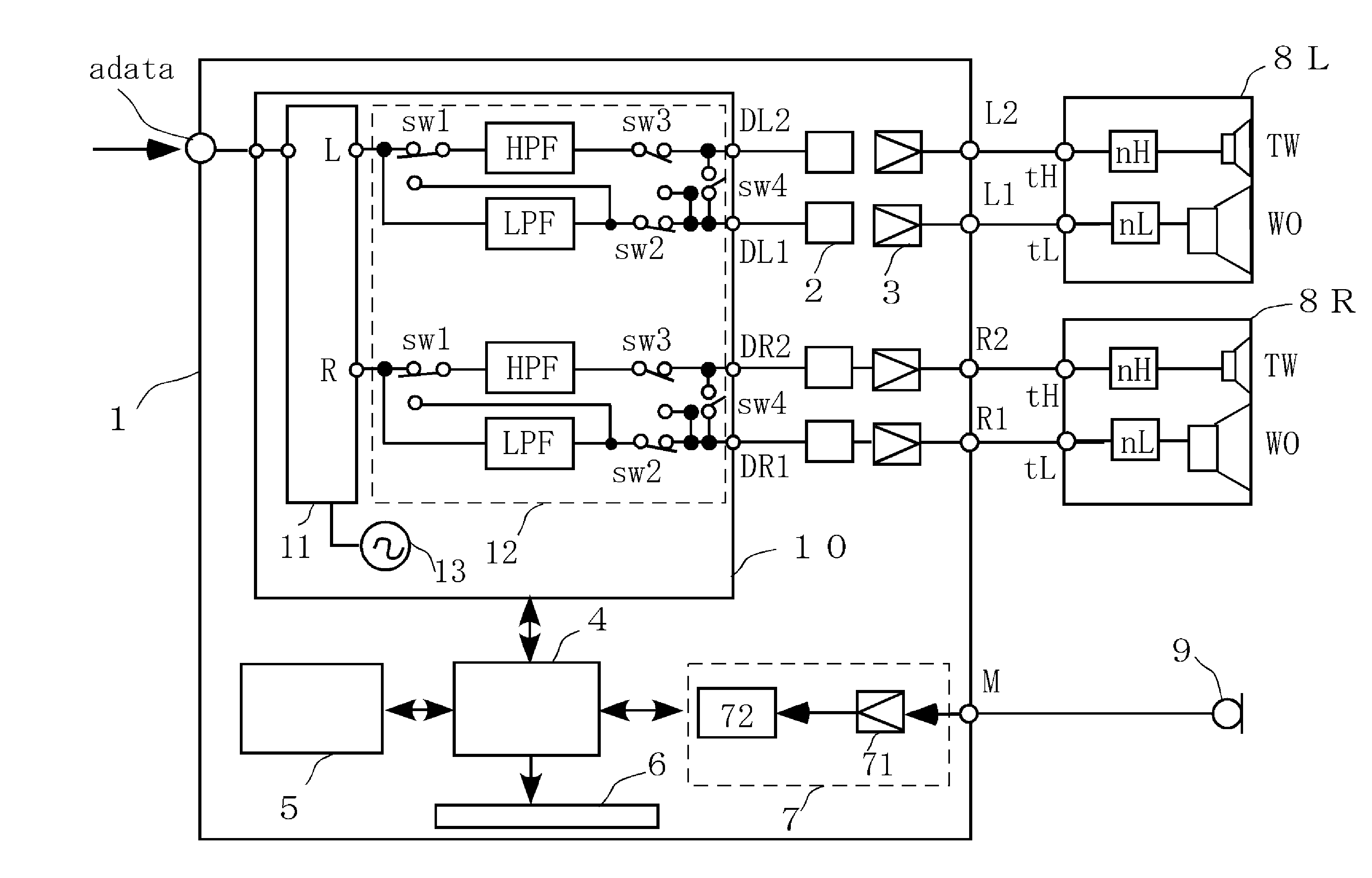
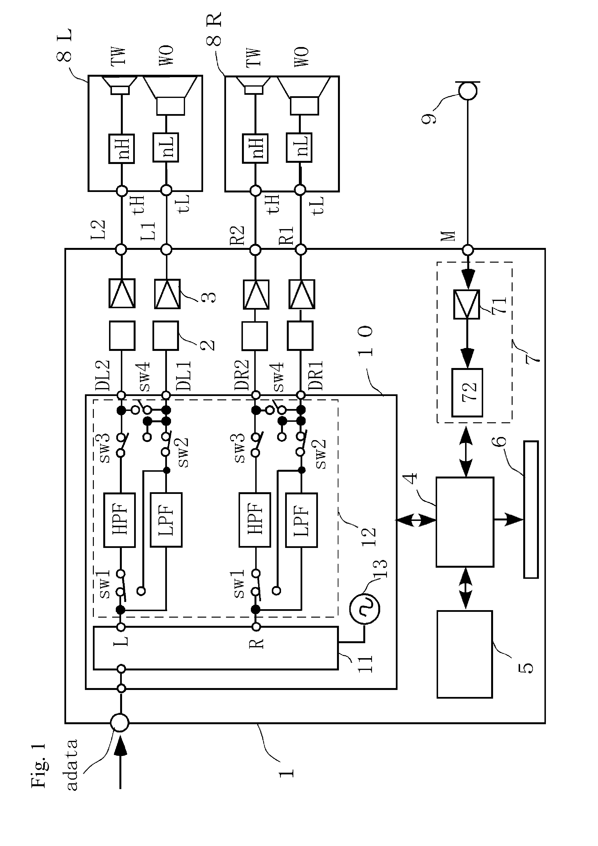
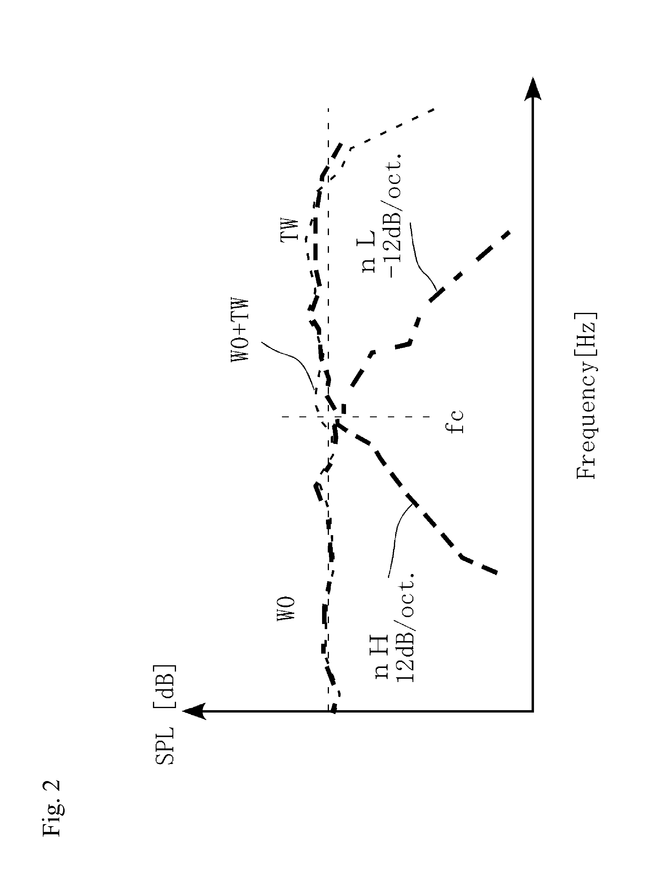
[0042]FIG. 1 is a diagram describing the sound reproducing system according to a preferred embodiment of the present invention. Concretely, the sound reproducing system includes an amplifier device 1 having the channel divider, a speaker system 8 and a microphone 9 connected to the amplifier device 1. FIG. 1 is a block diagram illustrating their internal constitutions. FIGS. 2, 4 and 6 are graphs describing a sound pressure frequency characteristic of the speaker system 8, and FIGS. 3 and 5 are graphs describing a crossover characteristic of the channel divider in the amplifier device 1. Illustration and description of some constitutions and internal structures that are not necessary for...


PUM


Abstract

A channel divider that can suitably set a crossover frequency when a biwiring-connectable multiway speaker system including network circuits are used is provided. The channel divider includes a low-pass filter LPF and a high-pass filter HPF for dividing a band of a sound signal into a first output signal and a second output signal so as to output the signals, and a control circuit for controlling the filters. The channel divider has a sound output mode in which the control circuit sets a cutoff frequency fcL of LPF to a value higher than fc0 by about ⅙ to 1 Oct., sets a cutoff frequency fcH of HPF to a value lower than fc0 by about ⅙ to 1 Oct., and outputs the first output signal and the second output signal including frequency bands fcL to fcH when any crossover frequency fc0 for defining the band division is specified.

Description

BACKGROUND OF THE INVENTION[0001]1. Field of the Invention[0002]The present invention relates to a channel divider to be used for reproducing a sound signal through a multiway speaker system and a method for setting its crossover frequency. The invention particularly relates to the channel divider that can suitably set the crossover frequency of the channel divider and can satisfactorily reproduce a sound when a biwiring-connectable speaker system including network circuits are used.[0003]2. Description of the Related Art[0004]In multiway speaker systems including woofers for low-pitched reproduction and tweeters for high-pitched reproduction, network circuits for dividing a band of a sound signal amplified by an amplifier according to a reproduction frequency band of each speaker unit are generally provided. In recent years, the following speaker systems where a network circuit corresponding to a woofer and a network circuit corresponding to a tweeter can be independent from each o...

Claims


Application Information

Patent Timeline
IPC IPC(8): H04R3/14
CPCH04R3/14
Inventor TAKEMURA, KAZUMASA
Owner ONKYO KK
Why Eureka
Try Eureka