Apparatus and lower thread winding-spool for detecting the ending region of lower thread of sewing machine

a technology of sewing machine and end region, which is applied in the field of sewing machines, can solve the problems of production cost increase or productivity decrease, production cost increase, and inferior quality or re-work of sewing operation

Inactive Publication Date: 2013-07-04
BOBBINTEL
View PDF7 Cites 6 Cited by
  • Summary
  • Abstract
  • Description
  • Claims
  • Application Information

AI Technical Summary

Benefits of technology

[0010]The present invention provides a lower thread ending region detection apparatus (abbreviated as LTERDA in the present invention), which will solve the aforementioned problems through accurately detecting the situation of the lower thread reaching the ending region as well as the rotation of the thread bobbin; being small, simple and problem-free in applying to existing sewing machines; minimizing production costs; causing no changes to existing thread bobbin production process; and preventing the increase of the thread bobbin production cost or the arise of quality related problems.
[0011]The present invention also provides the LTERDA that is able to easily and accurately detect the situation of the lower thread being broken (abbreviated as LTBB in the present invention) in addition to detecting the situation of the lower thread reaching the ending region (abbreviated as LTRER in the present invention).
[0012]The present invention also provides a bobbin and bobbin core (which are collectively termed as lower thread winding-spool in the present invention) which support the LTERDA to easily and accurately detect the situation of the LTRER.TECHNICAL SOLUTION

Problems solved by technology

Therefore, faulty stitchings happen due to being unable to see and detect the exhaustion or breakage of lower thread during sewing operation, and results in inferior quality or re-work of sewing operation.
As a result, production cost may increase or productivity may decrease.
Therefore, these methods are extremely wasteful in terms of time as well as labor force, and thus, production costs increase while productivity decreases and additional quality related problems occur.
Furthermore, these methods do not provide any means of detecting the thread bobbin's rotation in order to determine the situation of the lower thread being broken, and thus, an entirely separate device and mechanism must be additionally used.
The methods sticking a light reflective tape, a light polarizing reflective tape, or a bar code tape (these are collectively termed as reflecting tape hereinafter) to the bobbin core and detecting the light reflected from the reflecting tape, which is exposed when the lower thread is almost exhausted, are nearly impossible to be used for existing sewing machines.
This is because there is no space to attach a light emitting unit and a light receiving unit inside the BC, and it is very inconvenient to install the electric wire that delivers the output signal from the light receiving unit to an alerting device outside.
Specifically, as the BC's interior wall possesses a smooth surface made of a metallic substance, it is very difficult to accurately illuminate light onto the reflective tape attached on the small cylindrical bobbin core and accurately detect the reflected light without scattering of reflection.
Furthermore, as severe shaking occurs during the sewing operation, it becomes very difficult for the two light units to remain accurately aligned with the reflective tape attached on the small cylindrical bobbin core.
In actuality, if such methods were to be employed, the existing sewing machine structure would have to undergo drastic modification, or the hook device as well as the BC and other numerous existing devices used in the sewing machine must be exchanged with specially designed products, resulting in expensive costs and thus, make them almost impossible to be used for existing sewing machines.
In addition, these methods do not provide any means of detecting the thread bobbin's rotation in order to determine the situation of the lower thread being broken.
By the way, the automation process of sticking the reflecting tape to the bobbin core is not only difficult but very expensive in terms of production costs.
That is, it is very difficult in actuality to completely automate the process of sticking an extremely small reflective tape one by one to a cylindrical bobbin core made of plastic material; therefore, not only a lot of labor force is required, but also a lot of quality related problems are generated during the process, and results in the production costs being much greater than those of the process using just bobbin core made of plastic material.
In addition, as the lower thread has to be wound on the slippery reflecting tape during the thread winding process, the lower thread will be wound unevenly and results in the occurrence of an additional quality related problem.
These methods must not only modify the existing lower thread winding process, in which the lower thread was wound in only one direction, but also exchange all existing machines of winding lower thread, and additionally invoke severe quality related problems that occur as the already wound lower thread unravels during the process of winding in the opposite direction.
The methods attaching a rotation detection mark on the bobbin's sidewall flange and determining the number of rotations or the rotation speed of the thread bobbin are fundamentally unable to accurately detect the ending region of the lower thread.
Since, these methods may determine that the lower thread has reached the ending region, even though there is a lot of lower thread left, thus resulting in the waste of a lot of lower thread; or may not even detect it until the lower thread has been completely exhausted.
The reasons are that the operator does not maintain a constant motor speed during sewing operation, and that the sudden start or stop of the motor causes false rotations of the thread bobbin located inside the BC; all of which make it difficult to calculate the rotation speed of the thread bobbin, and thus, there is a large margin for error in detecting the lower thread ending region based on calculating rotation speed.
Also, the length of lower thread wound on each of the thread bobbin is not the same; thus, there is a large margin for error in determining the lower thread ending region based on counting the number of thread bobbin's rotation.
Besides, these methods are not useful for the thread bobbin which doesn't have a sidewall flange.
Therefore, these methods cannot support the recent market trend of industrial sewing machines and embroidery machines, a lot of which use the thread bobbins having only the bobbin core.
As reviewed above, previous methods for determining the situation of the lower thread reaching the ending region and the rotation of the thread bobbin have not been used in markets because of many problems: 1) invoke problems in the process of winding the thread on the bobbin core or the bobbin, 2) increase the production costs of the thread bobbins or quality related problems, 3) difficult to apply to existing sewing machines, 4) do not correctly detect the lower thread ending region of the thread bobbin, or 5) do not provide functions detecting the thread bobbin's rotation for determining the situation of the lower thread being broken.

Method used


Image

  • Apparatus and lower thread winding-spool for detecting the ending region of lower thread of sewing machine
  • Apparatus and lower thread winding-spool for detecting the ending region of lower thread of sewing machine
  • Apparatus and lower thread winding-spool for detecting the ending region of lower thread of sewing machine

Examples


first embodiment

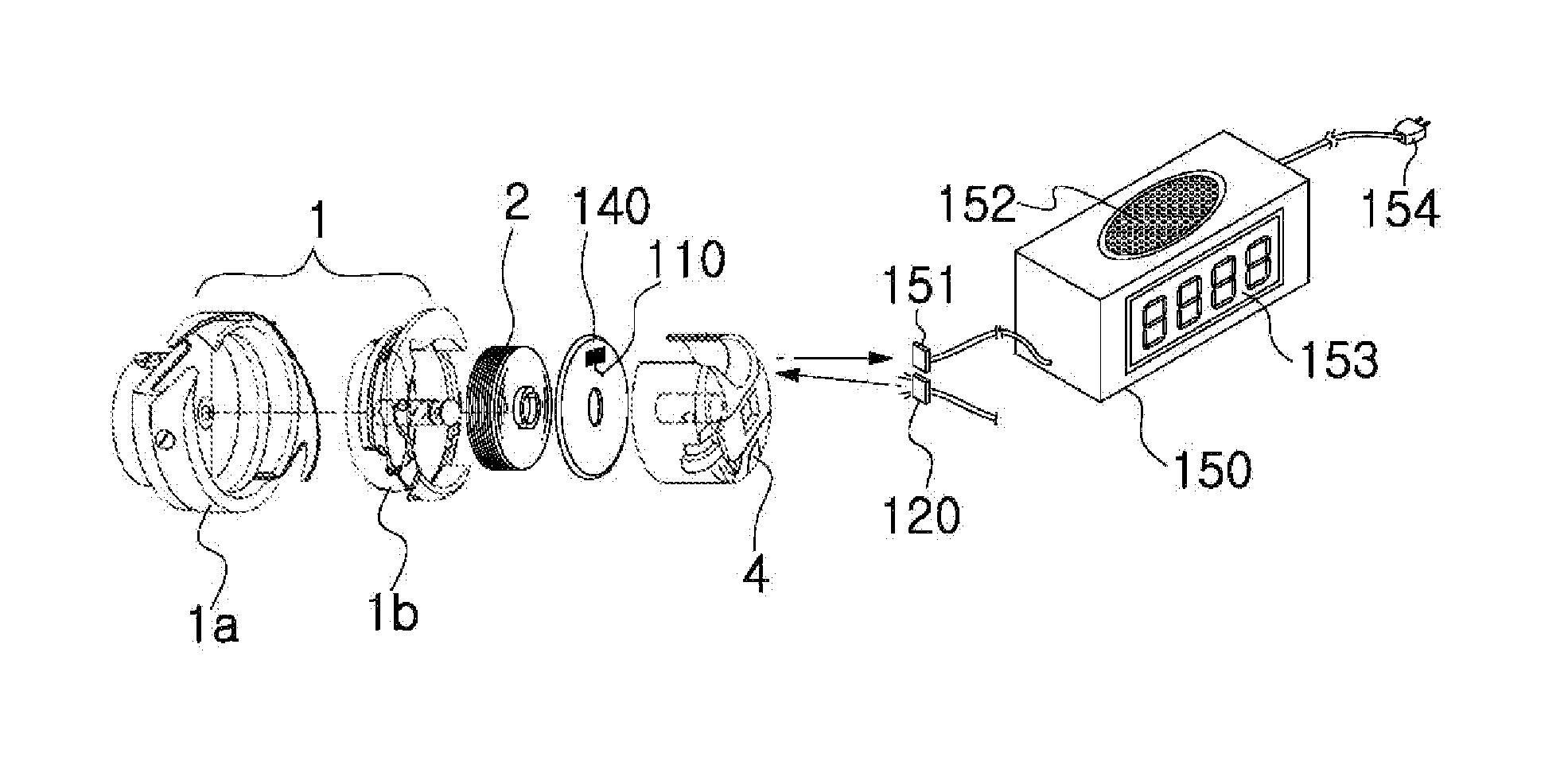
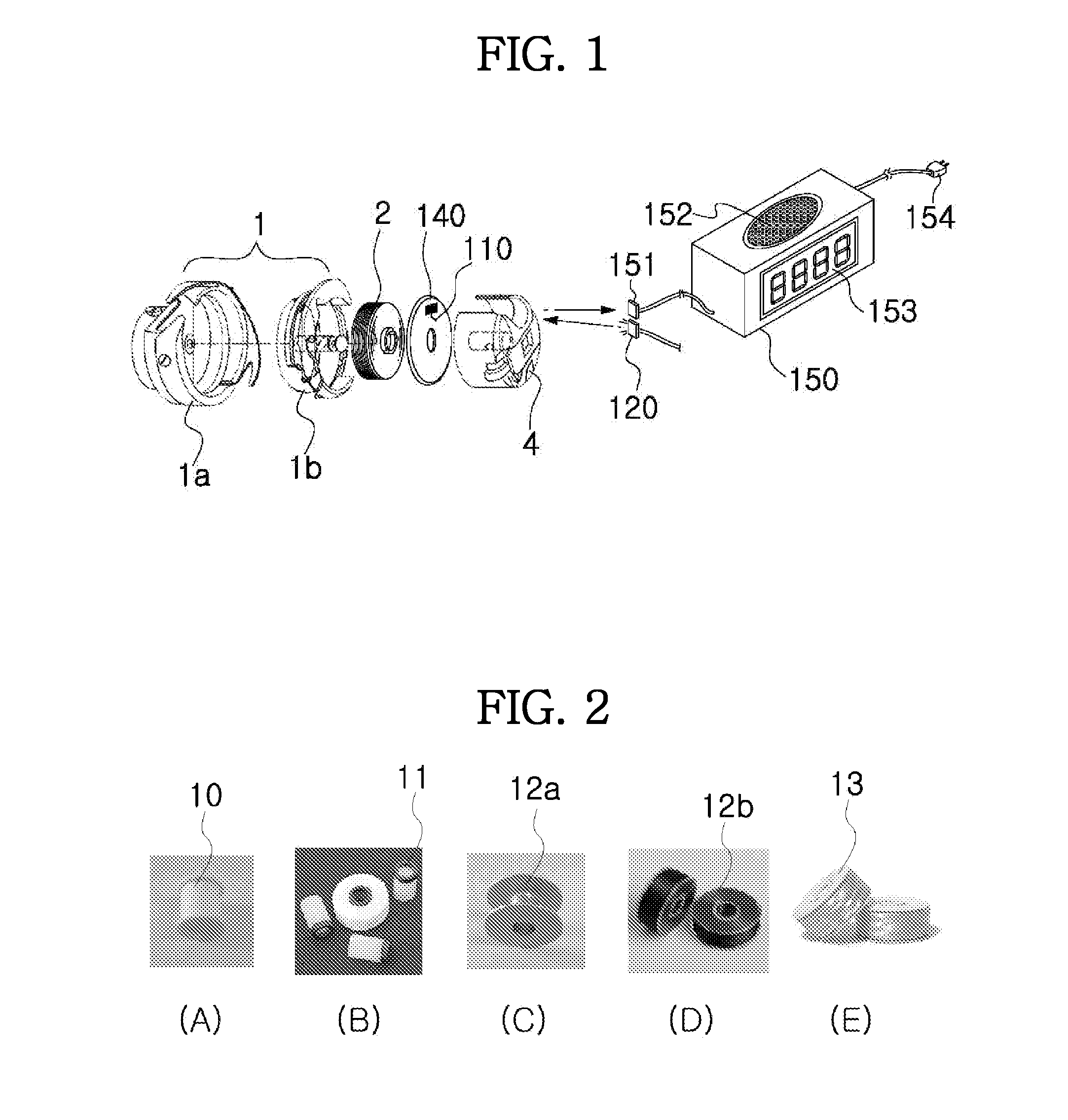
[0020]FIG. 1 illustrates an exploded perspective view showing the operating environment of the LTERDA based on the present invention.

[0021]FIG. 2 shows an embodiment of the various components composing the thread bobbin.

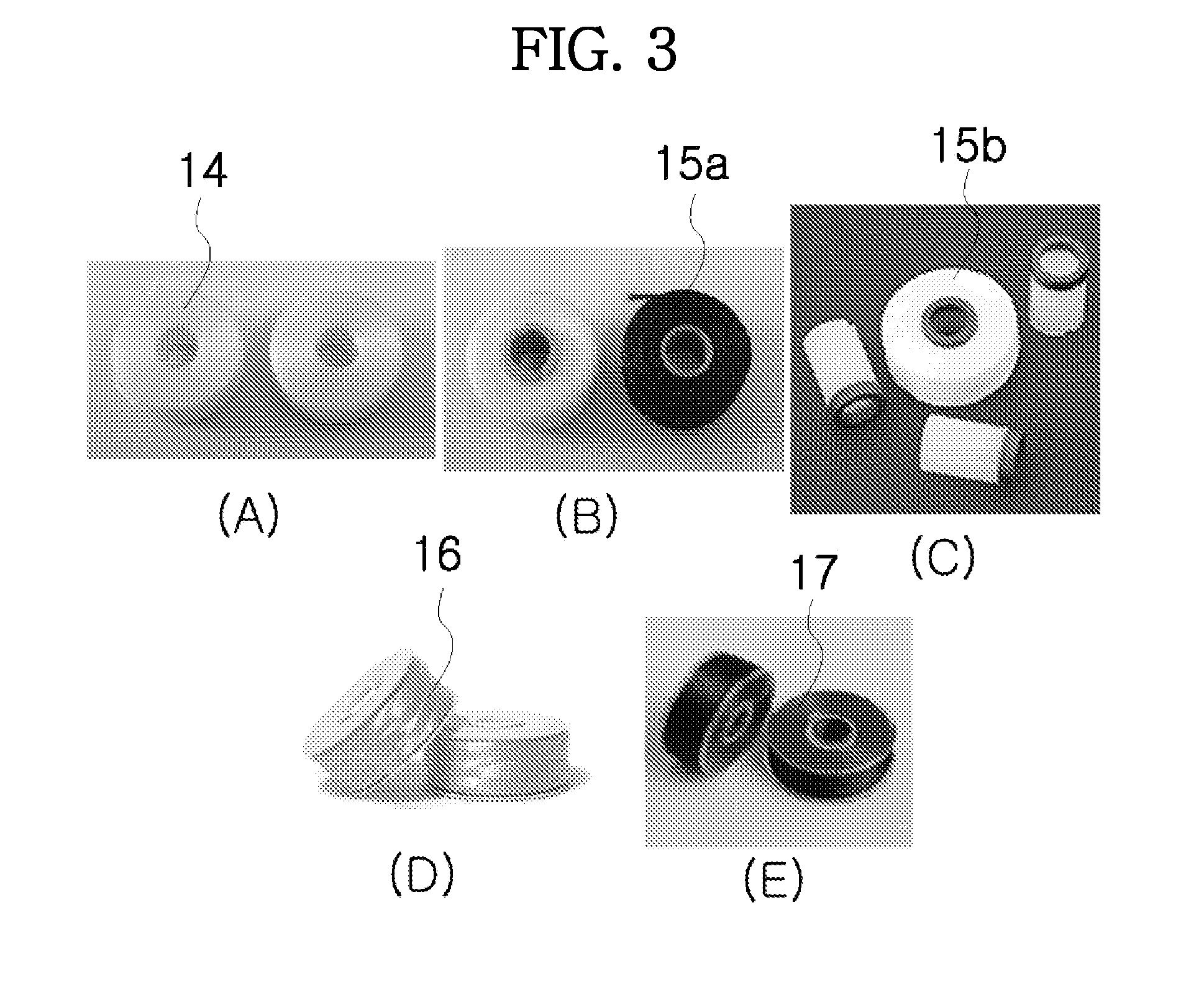
[0022]FIG. 3 shows some embodiments of the various types of thread bobbin.

[0023]FIG. 4 illustrates some embodiments of the lower thread ending region and the contact groove.

[0024]FIG. 5 illustrates a perspective side view (A) showing the BC and a plane view (B) showing the inside of the BC.

[0025]FIGS. 6A-6C illustrate some embodiments of the structures for combining the thread bobbin and the TBPP installed in the RTPL.

[0026]FIG. 7A illustrates an embodiment of the process of combining the RTPL and the thread bobbin.

[0027]FIGS. 7B-7C illustrate side views of embodiment of the structure, in which the RTPL and the thread bobbin are combined, showing that the lower thread ending region contacting part (abbreviated as LTERCP in the present invention) changes in position d...

second embodiment

[0038]FIG. 15 illustrates an exploded perspective view showing the operating environment of the LTERDA based on the present invention; wherein a motor rotation sensing unit (abbreviated as MRSU in the present invention) is added.

[0039]FIG. 16 illustrates an embodiment of the MRSU using a magnetic sensor which directly detects the rotation of the SMM.

[0040]FIG. 17 illustrates some embodiments of the structures, in which the LTERCPs are installed on the RTPL, showing that the position of the LCM rotates due to the effect of the PBP of the LTERCPs.

[0041]FIG. 18 shows an embodiment of bobbin having a tube, on a certain location of which one or more contact grooves are formed, and is made as a form surrounding at least a portion of the outer surface of the BSH.

[0042]FIGS. 19A-19C are diagrams representing the logical pattern of the detection signals output from the LRU and the MRSU.


PUM


Abstract

The present invention relates to a lower thread ending region detection apparatus (LTERDA) that prevents problems associated with poor quality and re-work resulting from false stitchings due to being unable to detect the exhaustion of the lower thread during the sewing operation. The lower thread ending region detection apparatus (LTERDA) comprises the following: a light control unit (LCU), which contacts a part of lower thread wound on a thread bobbin and activates or inactivates at least one of the functions of emitting light, reflecting light, passing or penetrating light and blocking light, due to the effect of the physical movement force (PMF) generated depending on whether the lower thread of the ending region is unwound; a light receiving unit (LRU), which receives the light transferred out by the light control unit (LCU) and outputs a detection signal; and a control and notification unit (CNU), which analyzes the detection signal output from the light receiving unit (LRU) to determine whether the lower thread has reached the ending region and outputs the result to the user.

Description

TECHNICAL FIELD[0001]The present invention relates to a sewing machine, specifically in regards to an apparatus that is able to easily and accurately detect the situation at which the lower thread (or bottom thread or bobbin thread) wound on a thread bobbin (pre-wound bobbin or lower thread bobbin) has reached the ending region and the situation at which the lower thread has been broken; and lower thread winding-spools which support the function of the apparatus.BACKGROUND ART[0002]Since the thread bobbin, once stored in a bobbin case (abbreviated as BC in the present invention), rests under the compartment of the sewing machine, the operator is unable to see it during sewing operation. Therefore, faulty stitchings happen due to being unable to see and detect the exhaustion or breakage of lower thread during sewing operation, and results in inferior quality or re-work of sewing operation. As a result, production cost may increase or productivity may decrease. In order to solve such ...

Claims


Application Information

Patent Timeline
Patent Type & Authority Applications(United States)
IPC IPC(8): D05B51/00
CPCD05B59/00D05B51/00D05B59/02D05B57/28D05B57/26
Inventor CHO, MYUNG RAI
Owner BOBBINTEL
Why Eureka
Try Eureka