Cycle wheel rim and method of manufacture

a cycle wheel and rim technology, applied in the direction of spoked wheels, cycles, transportation and packaging, etc., can solve the problems of reducing the thickness of b, breaking the extrusion die, and significant plastic deformation, so as to reduce the weight of the rim, improve rigidity, and manufacture quickly

Inactive Publication Date: 2013-07-04
MAVIC SA
View PDF10 Cites 2 Cited by
  • Summary
  • Abstract
  • Description
  • Claims
  • Application Information

AI Technical Summary

Benefits of technology

[0015]The foregoing are drawbacks that the present invention overcomes, particularly by providing a cycle wheel rim and a method for manufacturing such a rim, which makes it possible to reduce the weight of the rim while optimizing rigidity. In addition, the rim according to the invention can be manufactured quickly, and the manufacturing method prevents the occurrence of defects during the extrusion and bending of the section.

Problems solved by technology

Thus, for alloys that are typically used in the manufacture of rims, it is very risky to go below thicknesses of 0.85 mm, as doing so may quickly break the extrusion die.
In addition, the bending of a section causes significant plastic deformations, particularly in the zones that are away from the center of gravity of the cross section.
These substantial plastic deformations cause dislocations of the grains of the material which, in turn, can result in a surface finish known as “orange peel,” which is often considered unsightly.
Furthermore, overly thin lateral walls also generate local buckling of the walls of the section during bending, when subject to overly high compressive deformations.
This manufacturing method is relatively cumbersome to implement and, although the surface finish does become uniform, it remains quite rough.
Reducing the weight of the rim is not optimal because the bridge of the rim retains its initial thickness.
The machining is time-intensive and it is complex to implement, because it requires the use of a five-axis machine.
This leads to additional development costs and does not standardize the manufacturing method.
The useful life of rims is often limited by the appearance of cracks in the spoke fastening zone.
Once they occur, such cracks propagate very quickly in the spinning direction, quickly causing a rupture of the bridge.
This well-known fatigue phenomenon is due to the numerous load cycles to which the spokes are subjected at each turn of the wheel, on the one hand, and it is also accelerated by small surface defects which typically are longitudinal striations caused by friction of the metal in the die during the spinning operation, on the other hand.
Fatigue cracks generally occur in the area of the bridge of the rim, around the spoke fastening zones.

Method used


Image

  • Cycle wheel rim and method of manufacture
  • Cycle wheel rim and method of manufacture
  • Cycle wheel rim and method of manufacture

Examples


first embodiment

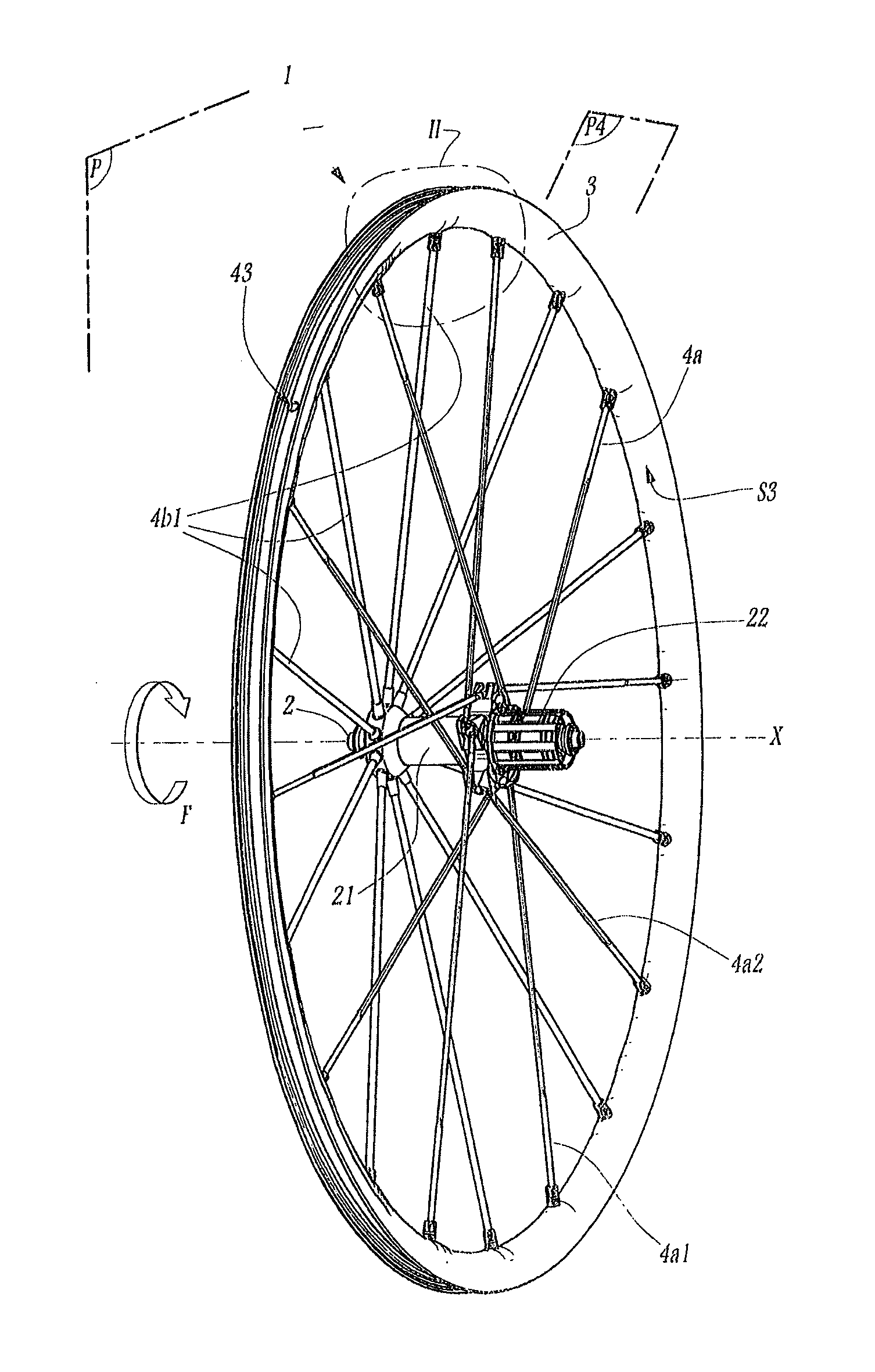
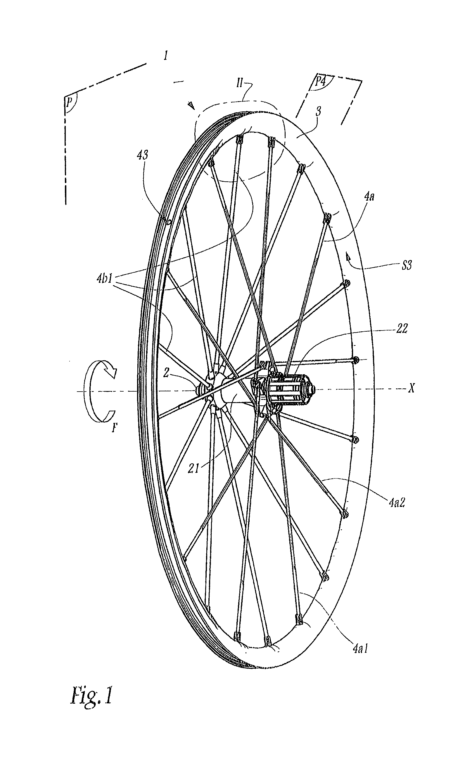
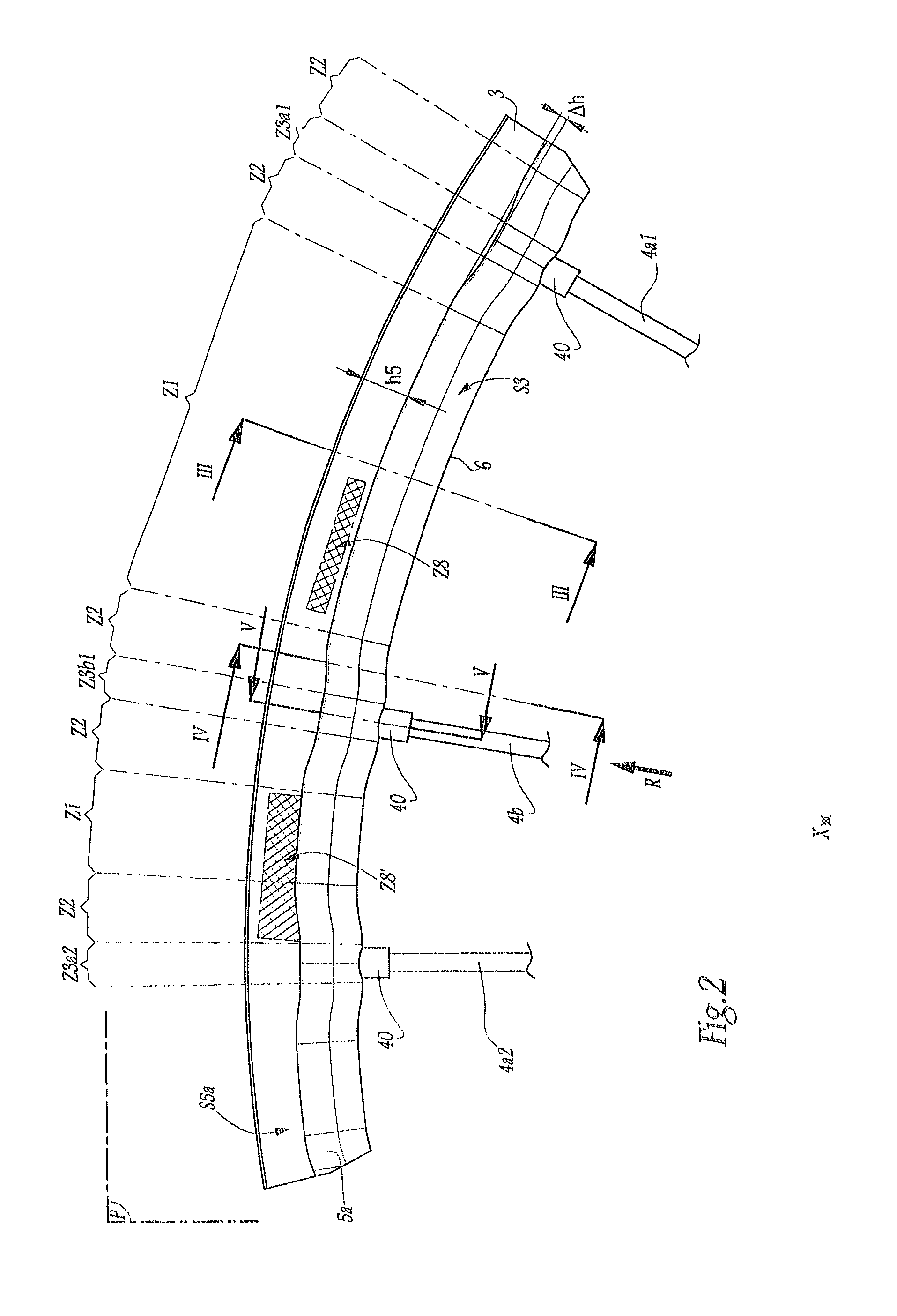
[0128]Similar to the rim 3, the rim 103 is divided into a plurality of zones Z1, Z2, Z3a1, Z3a2, Z3b1, which divide the circumference of the rim 103 into a plurality of angular sectors. As shown in FIGS. 12 to 15, the thickness e106 of the bridge 106 varies, depending upon the zone Z1, Z2, Z3a1, Z3a2, Z3b1 of the rim 103, in a manner similar to the rim 3 of the

[0129]The thickness e106 varies between a maximum thickness e106max, in the area of the transmission zones Z3a1, Z3a2, Z3b1, and a minimum thickness e106min, in the area of the intermediate zones Z1. In the area of the transition zones Z2, the thickness e106 is equal to an intermediate thickness between the minimum thickness e106min and the maximum thickness e106max.

[0130]The maximum thickness el06max of the transmission zones Z3a1 of the driving spokes 4a2 is greater than the maximum thickness e106max of the transmission zones Z3a2 of the non-driving spokes 4a1. The thickness e106max of the transmission zones Z3b1 of the spok...

third embodiment

[0156]The thicknesses e306 and e360 of the rim 303 and of the section 330 may be selected to be equal to the thicknesses e206 and e230 of the rim 203 and of the section 230 according to the

fifth embodiment

[0157]The following description relates to the invention, in which a rim, not shown, is made from the section 330 of FIG. 18.

[0158]The method for manufacturing this rim is generally similar to that for the rim 303. However, in the machining 1007, only a median zone Z306 of the outer surface of the bridge 306 is machined, over the entire circumference of the rim. Thus, the bridge 306 is not machined in its entirety. The median zone Z306 has a transverse width L306, measured perpendicular to the median plane P and greater than or equal to 4 mm. Thus, the bridge 306 is machined in the vicinity of all of the zones of attachment of the spokes 4a1, 4a2, 4b1, in the locations in which the mechanical stresses are the most substantial. Machining the bridge 306 only in the area of the median zone Z6 delays the appearance of cracks that might be initiated when the rim is used and subject to conditions causing fatigue. For example, it is possible to machine the intermediate zones Z1 only, or bo...


PUM

PropertyMeasurementUnit
transverse widthaaaaaaaaaa
thicknessaaaaaaaaaa
widthaaaaaaaaaa

Abstract

The invention includes a rim for a cycle wheel having a U-shaped radial cross section, with two lateral flanges located on opposite sides of a median plane of the rim and each demarcated by an outer surface facing away from the median plane, on the one hand, and a bridge connecting the flanges and comprising an outer surface facing toward the axis of rotation of the wheel, on the other hand. At least one median zone of the outer surface of the bridge, which has a transverse width measured perpendicular to the median plane and greater than 4 mm, is machined over the entire circumference of the rim.

Description

CROSS-REFERENCE TO RELATED APPLICATION[0001]This application is based upon French Patent Application No. 12 / 00021, filed Jan. 4, 2012, the disclosure of which is hereby incorporated by reference thereto in its entirety, and the priority of which is claimed under 35 U.S.C. §119.BACKGROUND[0002]1. Field of the Invention[0003]The invention relates to a rim for a cycle wheel, and a method for manufacturing such a rim.[0004]2. Background Information[0005]Conventionally, a cycle wheel rim is annular and has a U-shaped radial cross section, with two lateral flanges that are generally perpendicular to the axis of rotation of the wheel and a bridge that connects the lateral flanges and is oriented so as to be opposite the axis of rotation of the wheel. In the case of a spoked wheel, the spokes are generally fastened to the bridge of the rim.[0006]To manufacture a cycle wheel rim, it is known to make a rectilinear section by extruding or spinning a metal alloy, such as an aluminum alloy, for ...

Claims


Application Information

Patent Timeline
Patent Type & Authority Applications(United States)
IPC IPC(8): B60B21/00B60B31/00B60B1/02
CPCB60B21/00Y10T29/49506B60B31/005B60B21/025B60B21/026B60B21/062B60B21/08B60B2310/211B60B2310/232B60B2310/234B60B2360/104B60B2360/1458B60B2900/321B60Y2200/13B60Y2200/134B60B1/02
Inventor ALEXANDRE, BERENGERMERCAT, JEAN-PIERRE
Owner MAVIC SA
Why Eureka
Try Eureka