High-voltage voltage divider and connector comprising said divider

a voltage divider and high-voltage technology, applied in the field of voltage dividers, can solve the problem of resistance not being aligned, and achieve the effect of space saving and stable accuracy

Inactive Publication Date: 2013-07-04
ARTECHE LANTEGI ELKARTEA
View PDF5 Cites 8 Cited by
  • Summary
  • Abstract
  • Description
  • Claims
  • Application Information

AI Technical Summary

Benefits of technology

[0007]The object of the invention is to provide a voltage divider which is capable of space saving while at the same time assuring an optimum insulation and providing a stable accuracy. To that end, in a first aspect, the invention proposes a resistive voltage divider comprising a plurality n of resistive elements in a configuration wherein the angles m=n−1 between each pair of elements are between 180° and 10°, and wherein the group of elements is arranged on an insulating support the shape of which is such that the creepage distance of said support is equal to or longer than the sum of the creepage distances of the individual resistances.
[0008]The function of the support is to physic...

Problems solved by technology

For many applications, the resistances cannot be aligned (...

Method used


Image

  • High-voltage voltage divider and connector comprising said divider
  • High-voltage voltage divider and connector comprising said divider
  • High-voltage voltage divider and connector comprising said divider

Examples


Embodiment Construction

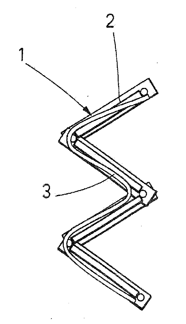
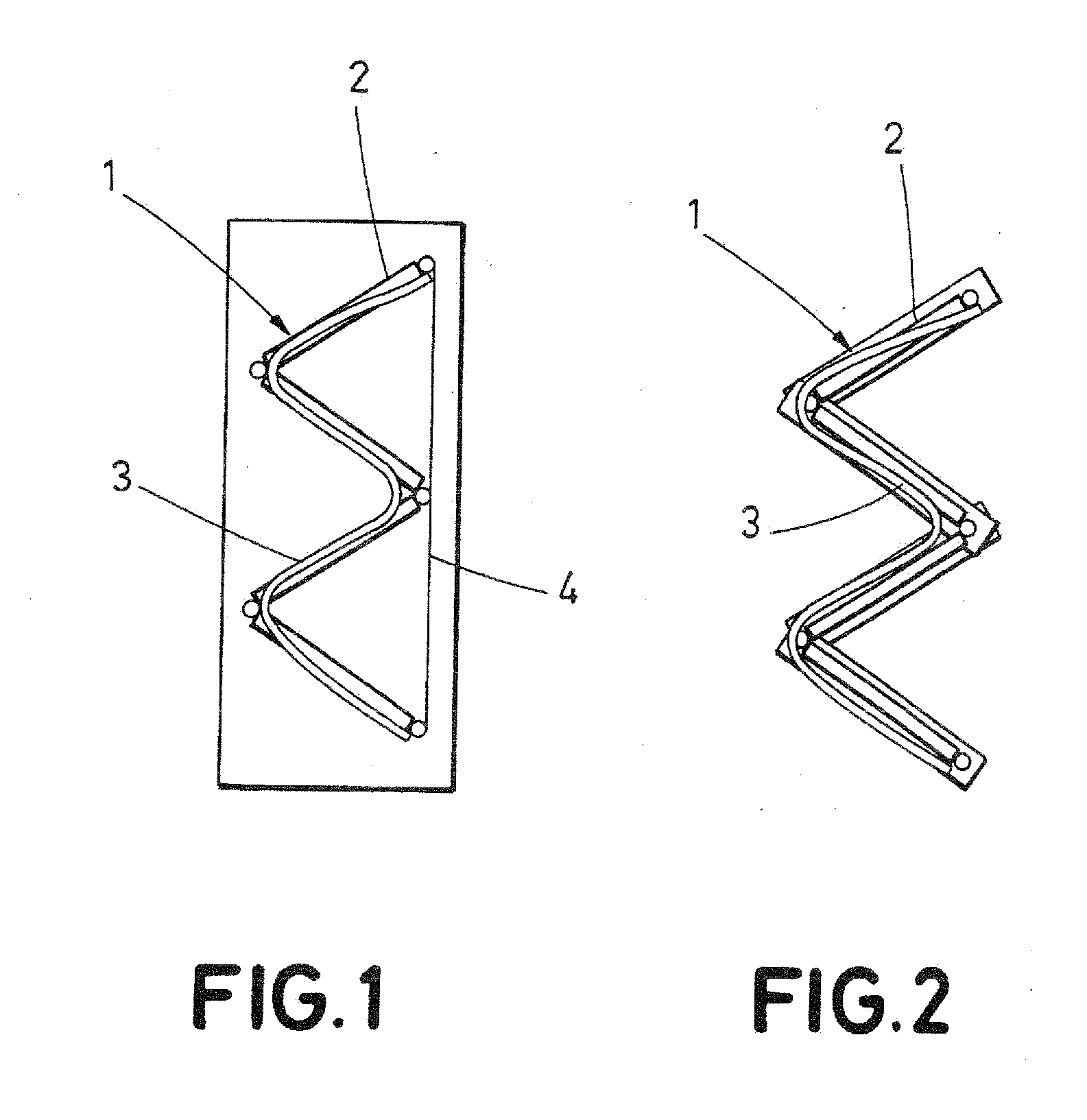
[0015]Referring to FIG. 2 which shows a preferred example of the invention, the insulating support (2) can be made of plastic, glass or it can be made directly from a support for printed circuit (PCNB). The angle between resistances (1) will be comprised between 180° and 10° to assure a correct operation of the device, without short-circuits but allowing space saving. The support can be zig-zag-shaped or sinusoid-shaped, corresponding approximately to the shape of the continuous distance joining the resistances. It can also have the alternative shape of FIG. 4, with 90° ladder shaped elements.

[0016]The zig-zag arrangement, sinusoid arrangement or the like which follows the shape of the divider allows, in addition to a stable mechanical support, maintaining the length of the creepage distance (1) and insulation distance of the entire device within defined parameters, there being no shortest path for the possible insulation malfunction. Compared with FIG. 1, corresponding to a divider...


PUM


Abstract

The present invention relates to a resistive voltage divider comprising a plurality n of resistive elements in a configuration wherein the angles m=n−1 between each pair of elements are between 180° and 10°, characterized in that the group of elements is supported by a dielectric the shape of which is such that it allows the creepage distance of the divider to be equal to or longer than the sum of creepage distances of the individual resistances. This arrangement allows a correct insulation of the device because it maintains the outer insulation since in the event of short-circuit the current will flow through the resistances and not through the support.

Description

FIELD OF THE INVENTION[0001]The present invention relates to a voltage divider and more particularly to a high-voltage resistive voltage divider. The divider can be housed inside a plug-in connector which can be plugged into a high-voltage power distribution cell.BACKGROUND OF THE INVENTION[0002]Voltage dividers are devices which allow converting a specific voltage applied to the high-voltage terminal into a lower voltage with a specific accuracy and transformation ratio, to thus enable having a proportional measurement of the voltage applied to the high-voltage terminal The basic operation principle of the divider is connecting a series of impedances to the voltage of a system. Thus the voltage is distributed among the impedances of the device, each impedance supporting a part of the total voltage of the system, thus the voltage of one of the impedances is proportional to the total voltage applied to the device. A resistive divider is a special case where the impedances are purely ...

Claims


Application Information

Patent Timeline
IPC IPC(8): H03H7/00
CPCH01C1/16H01C13/02H01C3/10G01R15/04H03H7/00
Inventor GARABIETA ARTIAGOITIA, INAKIMONTERO BOUZA, ALFONSO
Owner ARTECHE LANTEGI ELKARTEA
Why Eureka
Try Eureka