Ethernet for avionics

a communication network and avionics technology, applied in the field of system and a communication network in avionics, can solve the problems of excessive wiring, failure to meet one or several of these demands, so as to achieve high bandwidth and increase determinism

Inactive Publication Date: 2013-07-04
SAAB AB
View PDF3 Cites 37 Cited by
  • Summary
  • Abstract
  • Description
  • Claims
  • Application Information

AI Technical Summary

Benefits of technology

[0012]It is therefore an objective of the present invention to provide a system and a method, which offer high bandwidth and increased determinism in regard of the data traffic within an avionics communication network.

Problems solved by technology

Failure to meet one or several of these demands can in applications including “brake-by-wire” or “steer-by-wire” prove potentially dangerous.
In a system with many components requiring access to each other, this easily leads to excessive wiring and thereby increased weight, cost and complexity.
In an avionics system of today with high bandwidth requirement due to for example video processing resulting from increased use of image generating sensors, bandwidth of earlier protocol can prove insufficient.
Recently incentive has been raised within the field of avionics to implement more and more COTS hardware and software to reduce the need of specialized solutions with resulting higher cost.
However standard Ethernet was not originally developed with safety critical applications in mind.
Transmitted data have no guarantee to arrive at an intended receiver and may thus have to be retransmitted.
However, moving from dedicated communication protocols in attempts to reduce costs and increase bandwidth tends to decrease determinism.

Method used


Image

  • Ethernet for avionics
  • Ethernet for avionics
  • Ethernet for avionics

Examples


Embodiment Construction

[0033]The following examples relates to the case where a communication system is described with reference to aerial vehicles. However, various different applications are possible, e.g. for use in land, sea or space vehicles.

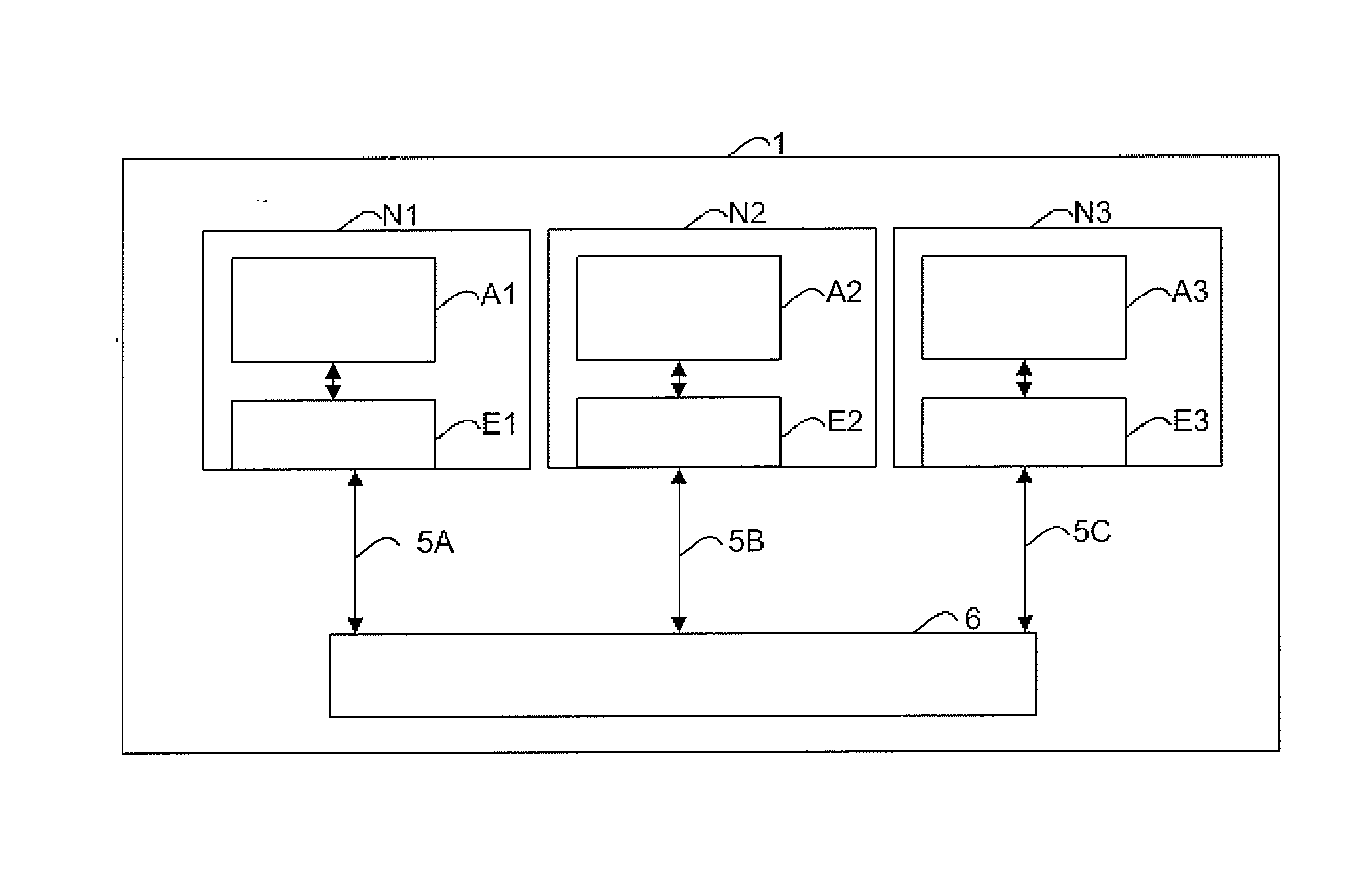
[0034]Referring to the drawings, and initially to FIG. 1, there is illustrated a block diagram of a communication network 1 in accordance with an example of the present invention. The communication network 1 also referred to in the description as the communication system comprises bidirectional transmission links 5A-5C, communicatively connecting a plurality of system nodes N1-N3, via a switch 6. The communication network 1 is configured to provide means for communication of data packets comprising units of data arranged in data messages between the system nodes N1-N3. The communication network 1 is based on standard Ethernet physical layer conformant with IEEE 802.3, such as for example 100 BASE-TX and / or 1000 BASE-T or the like. Each system node N1-N3 comprises...


PUM


Abstract

An avionics switched Ethernet network. A plurality of synchronized interconnected system nodes each includes an avionics module arranged to periodically provide a set of data messages. Each message includes a set of data variables. A network module couples the avionics module to the network. The network module includes a network interface unit arranged to provide for transmission of data packets including a number of the data messages from the avionics module. The network module of each system node includes a transmission control unit arranged to control the network interface unit to perform scheduled transmissions of the data packets. The transmission control unit is provided with access to a memory module. Each of the plurality of time-slots is statically allocated a predetermined number of data packets, each including a predetermined subset of data messages from the set of data messages.

Description

TECHNICAL FIELD[0001]The present invention relates to a system and a method for communication networks in avionics.BACKGROUND OF THE INVENTION[0002]In embedded control systems of today, developments in digital technology have enabled complex functionality. However as a direct result from the development, the need of additional system capacity provided by software and various components such as sensors, processors, display units, data buses and memory units is increasing.[0003]Apart from implementing more functionality and interconnectivity in control systems, using less Space Weight and Power, (SWaP) and a reduced number of cabling are further important drivers. Updates of embedded hardware and software during a products life span make adaptability and modularity another interesting design parameter. Other incentives include achieving cost efficient development, production and maintenance, where one possible route is to implement Commercial Off-The-Shelf (COTS) technology instead of...

Claims


Application Information

Patent Timeline
Patent Type & Authority Applications(United States)
IPC IPC(8): H04L12/56
CPCH04L12/4015H04L47/826H04L2012/4028
Inventor DANIELSSON, TORKELPETTERSSON, ANDERSGRIPSBORN, ANDERSHAKEGARD, JAN
Owner SAAB AB
Why Eureka
Try Eureka