Bolometer having frequency detection

a technology of bolometer and frequency detection, which is applied in the direction of material analysis, optical radiation measurement, instruments, etc., can solve the problem of increasing the overall noise of the thermistor

Inactive Publication Date: 2013-07-04
COMMISSARIAT A LENERGIE ATOMIQUE ET AUX ENERGIES ALTERNATIVES
View PDF13 Cites 19 Cited by
  • Summary
  • Abstract
  • Description
  • Claims
  • Application Information

AI Technical Summary

Problems solved by technology

This phenomenon increases the overall noise of the thermistor (Johnson's white noise and 1 / f noise) by modifying dynamic impedance and increasing local temperature.

Method used


Image

  • Bolometer having frequency detection
  • Bolometer having frequency detection
  • Bolometer having frequency detection

Examples


Embodiment Construction

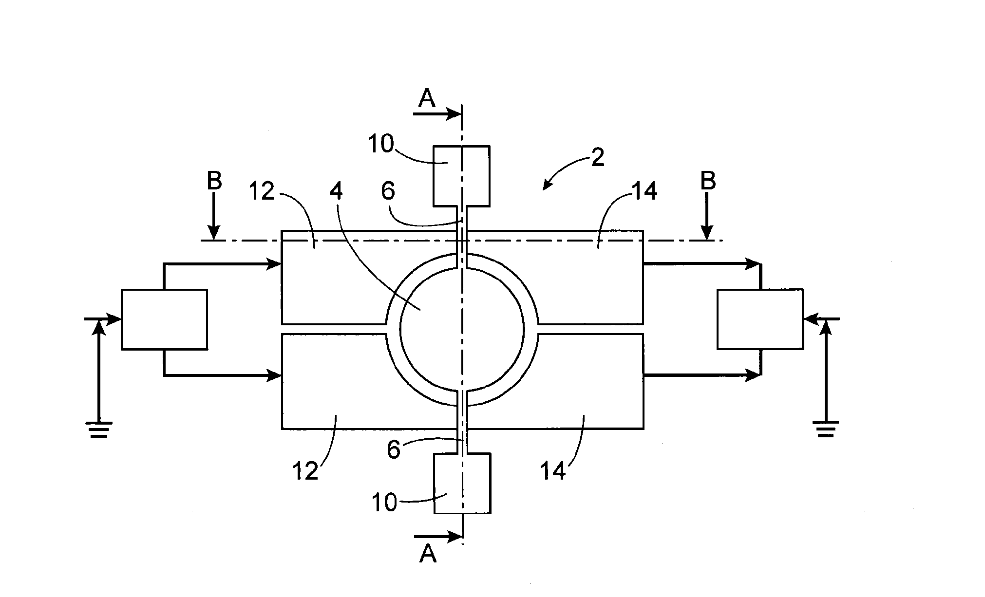
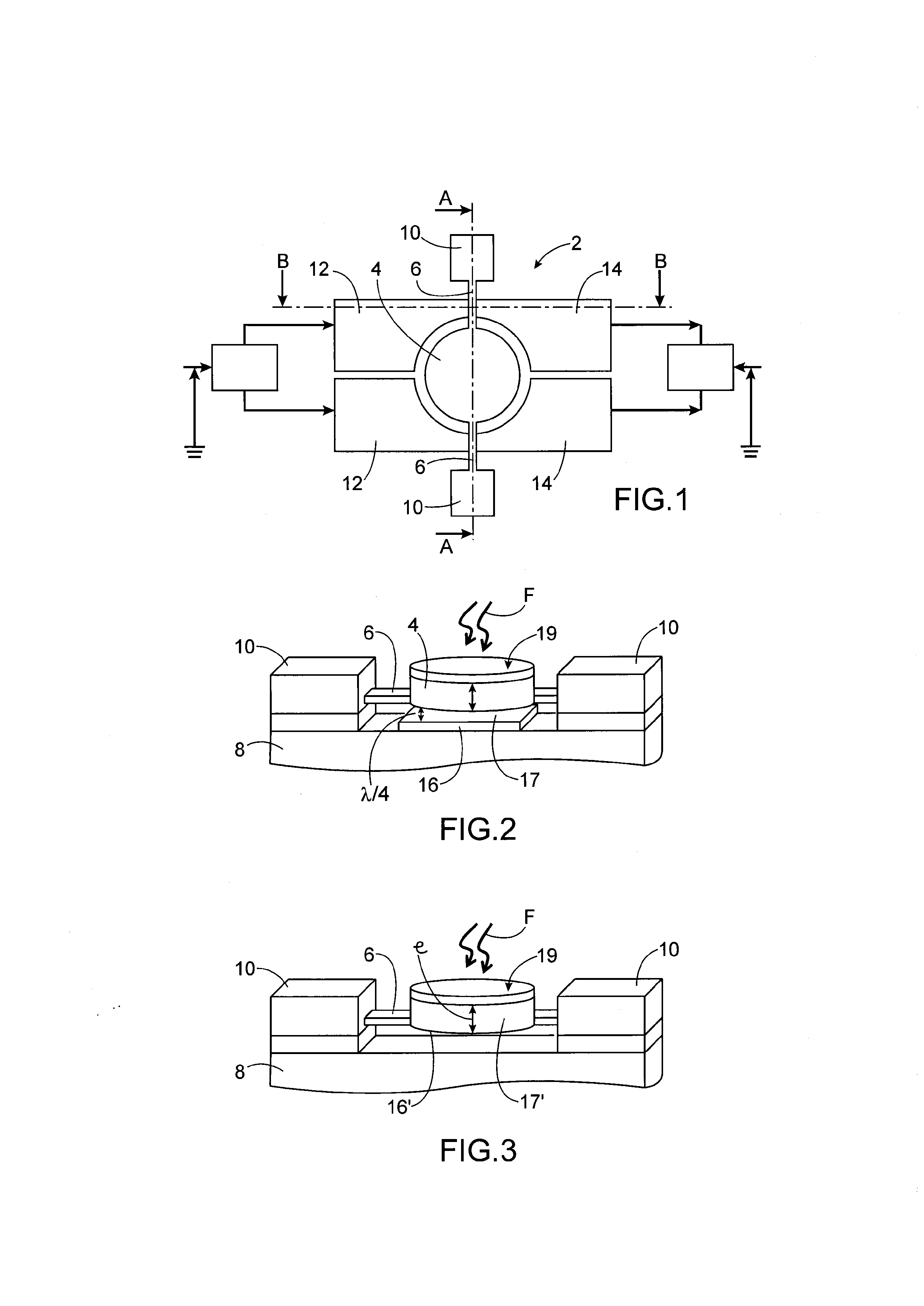
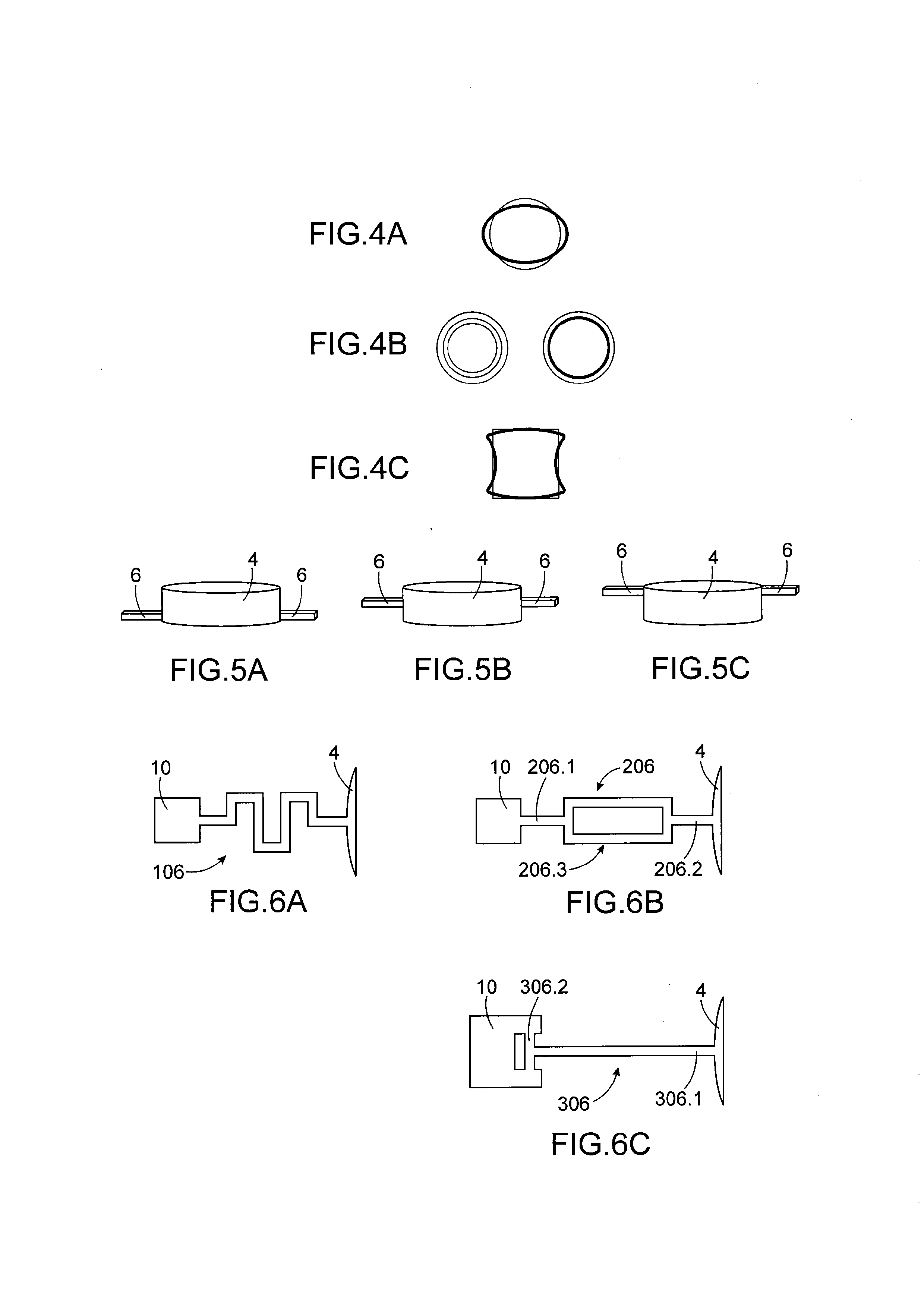
[0017]The foregoing objective is reached with a bolometer using at least one electromechanical micro- or nanostructure which is set in vibration at its resonance frequency. The variation in vibration frequency due to heating of the optical flux allows determination of the temperature of the environment in which the structure is located. The electromechanical micro- or nanostructure comprises a mass which deforms along its plane, thereby avoiding modification of the angle of incidence of the optical flux striking the mobile mass.

[0018]The bolometer of the invention therefore no longer uses electric resistances but a variation in vibration frequency, the mobile mass of the MEMS or NEMS structure forms the absorber of the bolometer.

[0019]In particularly advantageous manner, the variation in vibration frequency is detected by capacitive variation. 1 / f and Johnson noises are thereby avoided.

[0020]The phenomenon of self-heating due to polarization of the thermistor is therefore eliminated...


PUM


Abstract

A bolometer including: at least one electromechanical microsystem or nanosystem, the microsystem or nanosystem including a support and a mobile mass hung from beams above the support, the mobile mass forming an absorber of optical flux; actuation electrodes configured to set the mobile mass in vibration and arranged laterally relative to the mobile mass; and detection electrodes to detect variation in vibration frequency of the mobile mass arranged laterally relative to the mobile mass.

Description

TECHNICAL FIELD AND PRIOR ART[0001]The present invention relates to a bolometer with frequency detection using at least one MEMS or NEMS oscillator.[0002]By detection bolometer is meant any detection structure measuring a flow of particles, in particular optical particles in continuous or pulse mode.[0003]A microbolometer can be considered to be a thermometer sensitive to any rise in temperature caused by an optical flux emitted in the infrared, typically in a wavelength range of 3-5 μm or 8-14 μm.[0004]A prior art microbolometer is formed of a thermistor whose electric resistance varies in relation to the temperature rise caused by the optical flux to be measured. Such a bolometer is described for example in document “MEMS-based Uncooled Infrared Bolometer Arrays—A Review”, F. Niklaus, C. Vieider, H. Jakobsen, MEMS / MOEMS Technologies and Applications III, Proceedings of spie Vol. 6836D, 68360D (2007).[0005]Bolometers at ambient temperature are used for example in night vision syste...

Claims


Application Information

Patent Timeline
Patent Type & Authority Applications(United States)
IPC IPC(8): G01J5/28H01L31/18
CPCG01J5/02G01J5/023H01L31/18G01J5/44G01J5/28G01J5/40
Inventor DURAFFOURG, LAURENTANDREUCCI, PHILIPPE
Owner COMMISSARIAT A LENERGIE ATOMIQUE ET AUX ENERGIES ALTERNATIVES
Why Eureka
Try Eureka