Current steering element and non-volatile memory element incorporating current steering element

a technology of current steering element and non-volatile memory element, which is applied in the direction of basic electric elements, electrical apparatus, and semiconductor devices, can solve the problems of inability to correctly write and read data to and from the selected memory cell, slow operation of the element, and incorrect operation, so as to suppress the non-uniformity of voltage-current characteristics

Active Publication Date: 2013-07-04
PANASONIC SEMICON SOLUTIONS CO LTD
View PDF0 Cites 7 Cited by
  • Summary
  • Abstract
  • Description
  • Claims
  • Application Information

AI Technical Summary

Benefits of technology

[0049]The present invention has the above described configuration, and a bidirectional current steering element (element having a good bidirectional current steering characteristic with respect to an applied voltage) which can be incorporated into a variable resistance non-volatile memory device, and a non-volatile memory element and a non-volatile memory device including the current steering element can suppress non-uniformity of voltage-current characteristics among current steering elements.

Problems solved by technology

However, the unipolar variable resistance element has a problem that a pulse width of an electric pulse applied in resetting (attaining the higher-resistance state) is great, which makes the element operate at a slow speed.
If the allowable current of the bidirectional diode is less than the resistance changing current, the resistance state of the element does not change, which causes an incorrect operation.
If the leak current cannot be suppressed satisfactorily, it would become impossible to correctly write and read data to and from the selected memory cell.

Method used


Image

  • Current steering element and non-volatile memory element incorporating current steering element
  • Current steering element and non-volatile memory element incorporating current steering element
  • Current steering element and non-volatile memory element incorporating current steering element

Examples


embodiment 1

Configuration

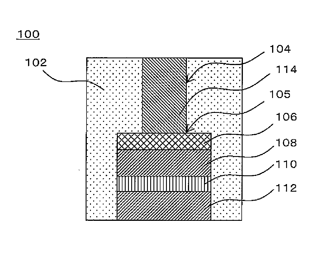
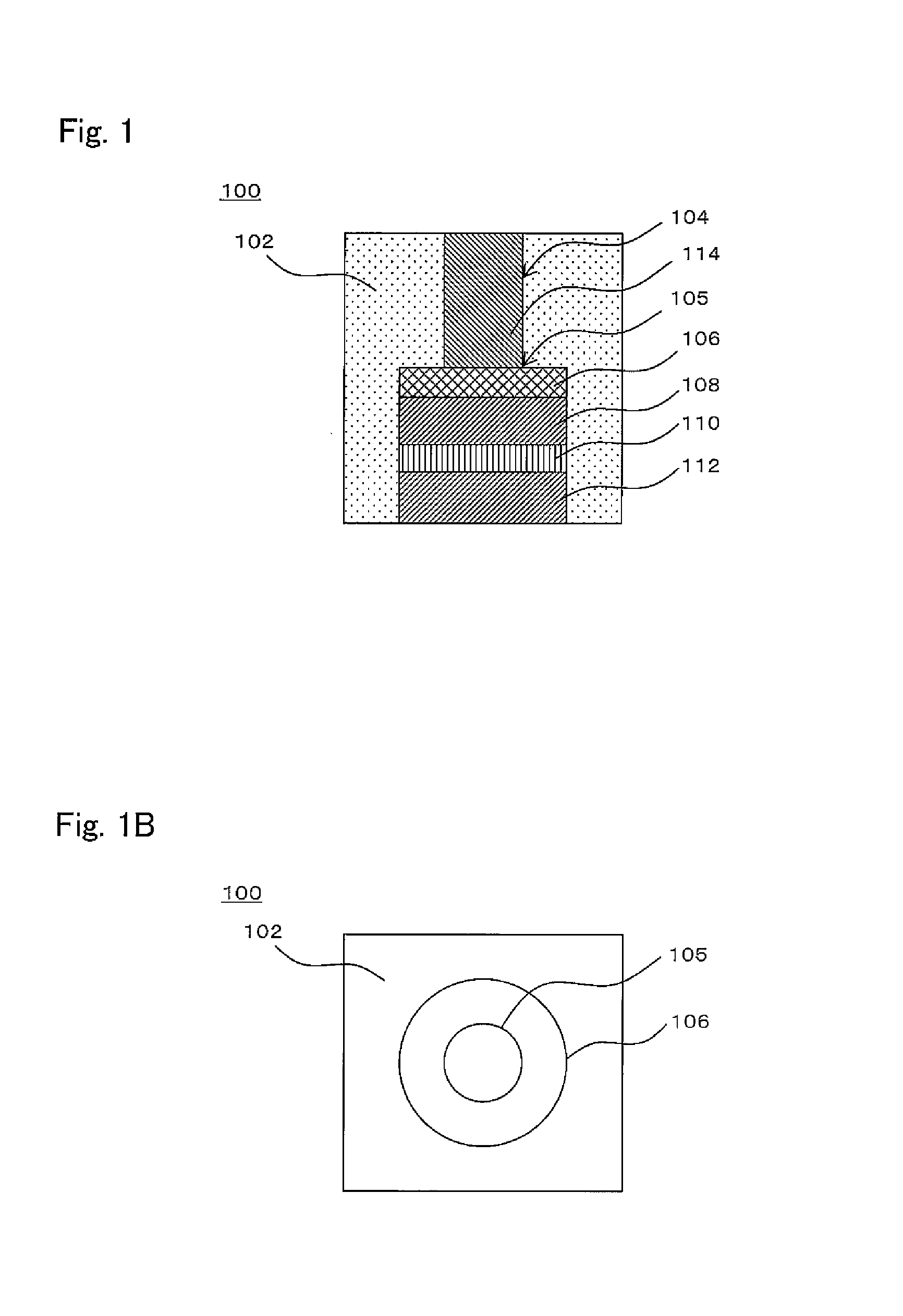
[0092]FIG. 1 is a view showing an exemplary schematic configuration of a current steering element according to an embodiment of the present invention. FIG. 1A is a cross-sectional view and FIG. 1B is a plan view when viewed from a thickness direction of an interlayer insulating layer.

[0093]As shown in FIG. 1A, a current steering element 100 is a current steering element formed to cover a lower opening of a via hole 104 formed in an interlayer insulating layer 102. The current steering element 100 includes a corrosion-suppressing layer 106 formed such that it covers an entire portion of a lower opening 105 of the via hole 104, a second electrode layer 108 (in the present embodiment, upper electrode 108) formed under the corrosion-suppressing layer 106 and comprising a material different from a material of the corrosion-suppressing layer 106, a current steering layer 110 formed under the second electrode layer 108 such that the current steering layer 110 is physically in ...

experiment example 1

[0119]In experiment example 1, a plurality of current steering elements were created for two kinds of configurations (wiring pattern 1, wiring pattern 2) which were different from each other in area of wire (floating wire, ungrounded lower wire) connected to the lower electrode, and their voltage-current characteristics were researched.

[0120]Initially, aluminum was deposited on the Si substrate and the lower wire 118 was formed by patterning. In the wiring pattern 1, the area of the lower wire 118 was set to about 69μm2. In the wiring pattern 2, the area of the lower wire 118 was set to about 6700 μm2.

[0121]On the substrate provided with the lower wire 118, the interlayer insulating layer 115 (final thickness on the lower wire: 200 nm) comprising SiO2 was formed. Thereafter, a lower via hole of a diameter 0.26 μm was formed by using a mask and by dry etching such that the wire was exposed in a bottom portion thereof, and a residual of a polymer remaining after the dry etching was re...

experiment example 2

[0131]In Experiment example 2, in order to study a cause of the alternation (property change) occurring in the upper electrode in Experiment example 1, the cross-section of the element was measured using a Scanning Auger Microprobe (SAM). In Experiment example 2, measurement was made for the sample which was extremely degraded in voltage-current characteristic (voltage-current characteristic which was difficult to measure), among samples having a configuration similar to that of the wiring pattern 2 in Experiment example 1 and created by the manufacturing method similar to that in Experiment example 1. This was probably because the degree of alternation of the upper electrodes 108 was considered to be greater in the sample which was extremely degraded in voltage-current characteristic.

[0132]FIG. 9 is a view showing results of observation of the current steering element in Experiment example 2. FIG. 9A shows a scanning electron microscope photograph of the cross-section. FIG. 9B show...


PUM


Abstract

A current steering element (100) formed such that the current steering element covers a lower opening (105) of a via hole (104) formed in an interlayer insulating layer (102), comprises: a corrosion-suppressing layer (106) formed on a lower side of a lower opening of the via hole such that the corrosion-suppressing layer covers an entire portion of the lower opening; a second electrode layer (108) formed under the corrosion-suppressing layer and comprising a material different from a material of the corrosion-suppressing layer; a current steering layer (110) formed under the second electrode layer such that the current steering layer is physically in contact with the second electrode layer; and a first electrode layer (112) formed under the current steering layer such that the first electrode layer is physically in contact with the current steering layer; and the first electrode layer, the current steering layer and the second electrode layer constitute one of a MSM diode and a MIM diode.

Description

TECHNICAL FIELD[0001]The present invention relates to a current steering element having a bidirectional current steering characteristic with respect to an applied voltage, and a non-volatile memory element including the current steering element.BACKGROUND ART[0002]In recent years, with progresses of digital technologies, electronic devices such as portable information devices and information home appliances have been developed to achieve higher functionalities. With achievement of the higher functionalities of the electronic devices, non-volatile memory devices incorporated into the electronic devices have been developed to provide a larger scale, higher-dense integration and a higher speed. The uses of the non-volatile memory devices have been spreading at a higher pace.[0003]Among them, there has been proposed a non-volatile memory device in which variable resistance elements are arranged in an array form. It is expected that the non-volatile memory device will realize a larger-sc...

Claims


Application Information

Patent Timeline
Patent Type & Authority Applications(United States)
IPC IPC(8): H01L45/00H01L21/768
CPCH01L27/101H01L45/00H01L45/04H01L45/1233H01L45/16H01L27/2409H01L27/2418H01L21/768H01L45/146H10B63/22H10B63/20H10N70/00H10N70/20H10N70/8833H10N70/826H10N70/011
Inventor MIYANAGA, RYOKOMIKAWA, TAKUMIHAYAKAWA, YUKIONINOMIYA, TAKEKIARITA, KOJI
Owner PANASONIC SEMICON SOLUTIONS CO LTD
Why Eureka
Try Eureka