Surgical fluid management systems and methods

Active Publication Date: 2013-07-04
BOSTON SCI SCIMED INC
View PDF8 Cites 74 Cited by
  • Summary
  • Abstract
  • Description
  • Claims
  • Application Information

AI Technical Summary

Benefits of technology

[0019]In further embodiments, the methods of the present invention may comprise sealing an access to the body space, for example the cervix when treating a uterus, to prevent the loss of distending fluid from the body cavity or space. Alternatively, fluid which is lost through the access to the body space may be captu

Problems solved by technology

One particular concern is the fact that fluid management systems typically administer the fluid under a pressure of up to 100 mm Hg or more which results in a significant risk that the dist

Method used


Image

  • Surgical fluid management systems and methods
  • Surgical fluid management systems and methods
  • Surgical fluid management systems and methods

Examples


Embodiment Construction

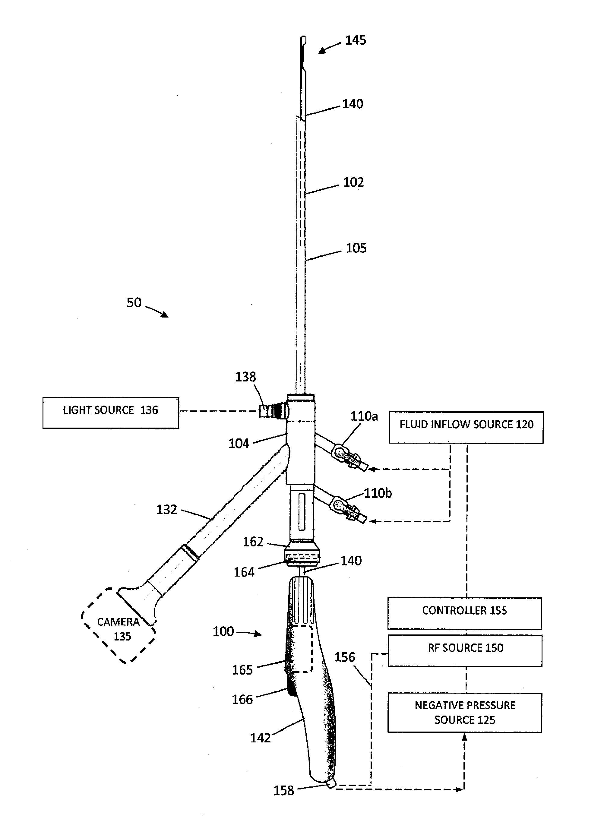
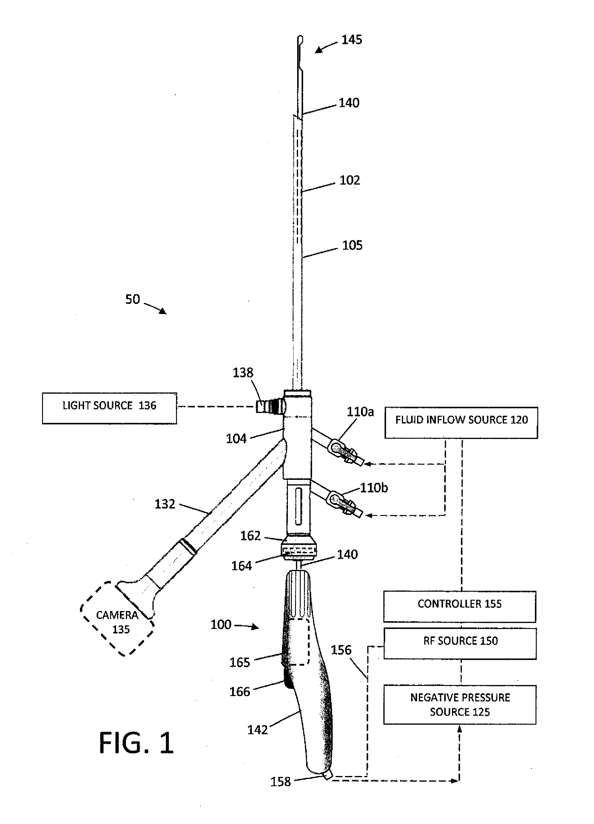
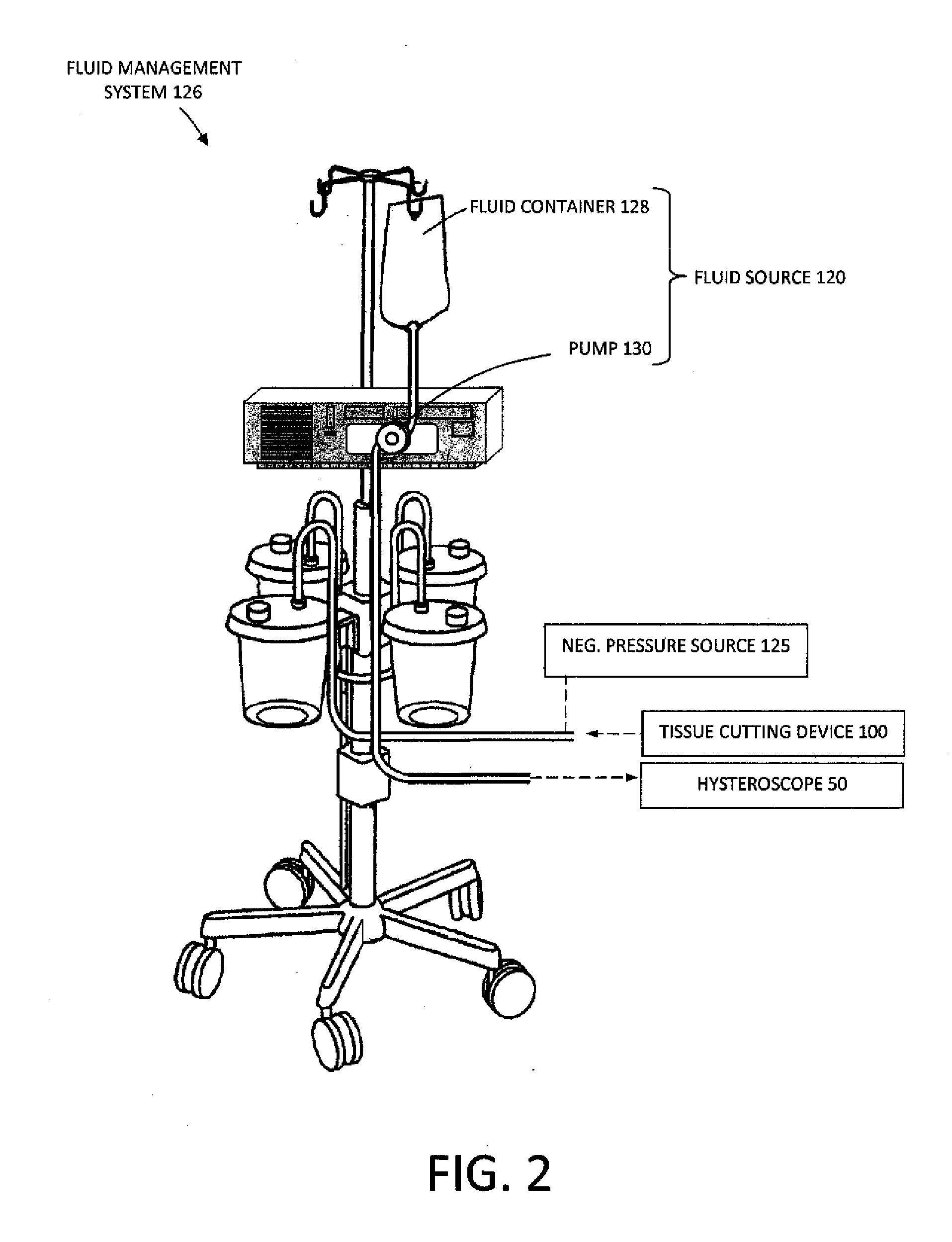
[0049]FIG. 1 illustrates an assembly that comprises an endoscope 50 used for hysteroscopy together with a tissue-extraction device 100 extending through a working channel 102 of the endoscope. The endoscope or hysteroscope 50 has a handle 104 coupled to an elongated shaft 105 having a diameter of 5 mm to 7 mm. The working channel 102 therein may be round, D-shaped or any other suitable shape. The endoscope shaft 105 is further configured with an optics channel 106 and one or more fluid inflow / outflow channels 108a, 108b (FIG. 3) that communicate with valve-connectors 110a, 110b configured for coupling to a fluid inflow source 120 thereto, or optionally a negative pressure source 125 (FIGS. 1-2). The fluid inflow source 120 is a component of a fluid management system 126 as is known in the art (FIG. 2) which comprises a fluid container 128 and pump mechanism 130 which pumps fluid through the hysteroscope 50 into the uterine cavity. As can be seen in FIG. 2, the fluid management syste...


PUM


Abstract

A fluid management system for use with a fluid reservoir includes an inflow pump and an outflow pump. The inflow pump is connectable to a probe for delivering a distention fluid to a body cavity. The outflow pump removes the distention fluid through the same probe, thus establishing a re-circulating volume of distention fluid within the body cavity. The removed fluid is filtered and returned to a fluid reservoir for eventual recycling to the body cavity. A controller adjusts the flow rates of the inflow pump and the outflow pump to maintain a pre-selected fluid pressure or volume within the body cavity.

Description

CROSS-REFERENCE TO RELATED APPLICATIONS[0001]This application claims the benefit of provisional application No. 61 / 502,750 (Attorney Docket No. 33291-714.101), filed on Jun. 29, 2011, and also the benefit of provisional application No. 61 / 503,497 (Attorney Docket No. 33291-715.101), filed on Jun. 30, 2011, the full disclosures of which are incorporated herein by reference.FIELD OF THE INVENTION[0002]The present invention relates surgical fluid management systems and methods, for example for use in distending the uterine cavity to allow cutting and extraction of uterine fibroid tissue, polyps and other abnormal uterine tissue.BACKGROUND OF THE INVENTION[0003]Uterine fibroids are non-cancerous tumors that develop in the wall of uterus. Such fibroids occur in a large percentage of the female population, with some studies indicating up to 40 percent of all women have fibroids. Uterine fibroids can grow over time to be several centimeters in diameter and symptoms can include menorrhagia,...

Claims


Application Information

Patent Timeline
IPC IPC(8): A61M1/00
CPCA61M1/0031A61M1/0058A61M1/008A61B17/42A61B18/1485A61M1/006A61B2018/00559A61B2018/00601A61B2017/4216A61M3/0229A61B2018/00196A61M2205/50A61M3/0208A61M3/0212A61M3/0216A61M3/022A61M1/777A61M1/74A61M1/84A61B17/3205A61B17/320016
Inventor TRUCKAI, CSABAGERMAIN, AARONKLEIN, KYLESHADDUCK, JOHN H.WALKER, MICHAEL D.ORCZY-TIMKO, BENEDECKLESKO, BALAZS
Owner BOSTON SCI SCIMED INC
Why Eureka
Try Eureka