Magnetic ranging tool and method

a magnetic ranging and measurement technology, applied in seismology, waterlogging using reradiation, instruments, etc., can solve the problems of limiting production, no production, and high cost of simultaneous access to both wells

Active Publication Date: 2013-07-04
SCHLUMBERGER TECH CORP
View PDF7 Cites 44 Cited by
  • Summary
  • Abstract
  • Description
  • Claims
  • Application Information

AI Technical Summary

Benefits of technology

[0010]The disclosed embodiments may provide various technical advantages. For example, since both the magnetic source and the magnetic field sensor are deployed in the magnetic ranging tool, ranging operations can be conducted without any access to the target well. Moreover, there is no requirement to permanently magnetize the target well prior to the ranging operation.
[0011]The disclosed embodiments may be further advantageous in that they enable both a separation distance and a dip angle between the drilling well and the target well to be computed. Obtaining the dip angle may be particularly advantageous in certain operations in that it is a predictive measure of a future separation distance. For example, in a twin well drilling operation, a nonzero dip angle indicates that the separation distance will either increase or decrease if the drilling direction remains unchanged. This may enable an operator to respond proactively rather than reactively in following the target well.

Problems solved by technology

Positioning the wells either too close or too far apart may severely limit production, or even result in no production.
Such continuous, simultaneous access to both wells tends to be labor and equipment intensive (and therefore expensive) and can also present safety concerns.
Misalignment can result in a misplaced twin well, which can have a significant negative impact on future well productivity.
Moreover, the steps taken to assure proper alignment (such as making magnetic field measurements at multiple longitudinal positions in one of the wells) are time consuming (and therefore expensive) and may further be problematic in deep wells.
For example, magnetizing large numbers of casing tubulars, storing the magnetized tubulars, and deploying the magnetized tubulars in the target well can introduce technical and logistical challenges.
In-situ magnetization of the target well casing string can also be challenging and requires temporary access to the target well.

Method used


Image

  • Magnetic ranging tool and method
  • Magnetic ranging tool and method
  • Magnetic ranging tool and method

Examples


Embodiment Construction

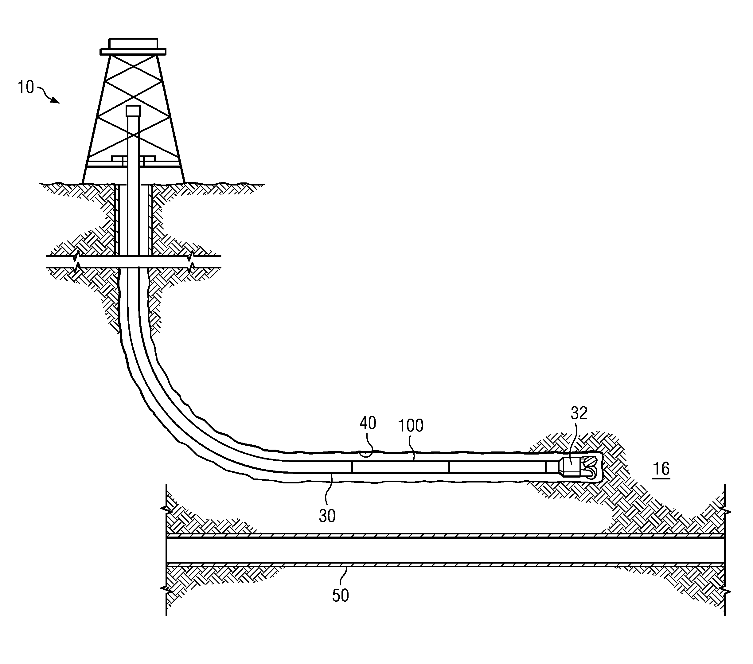
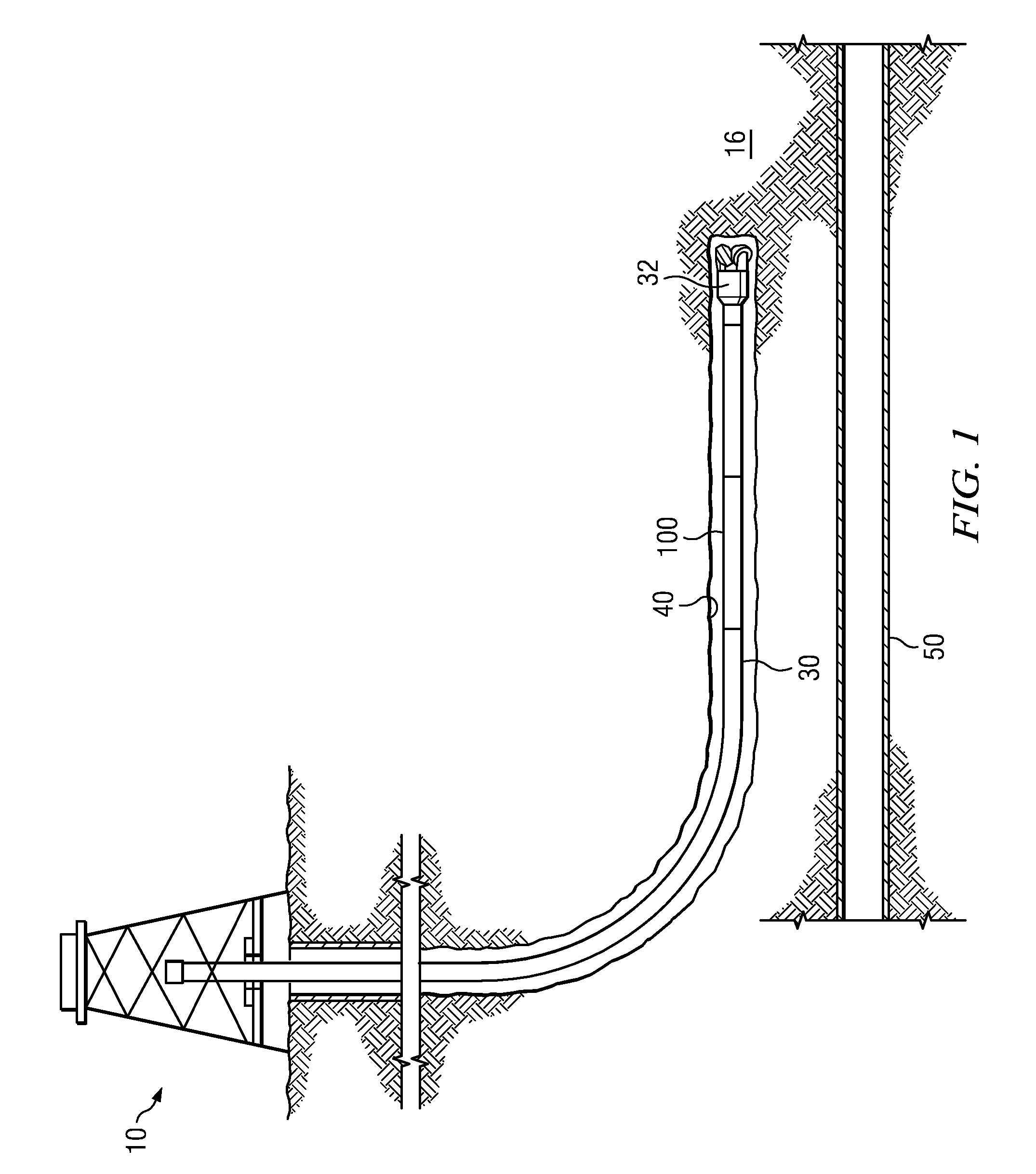
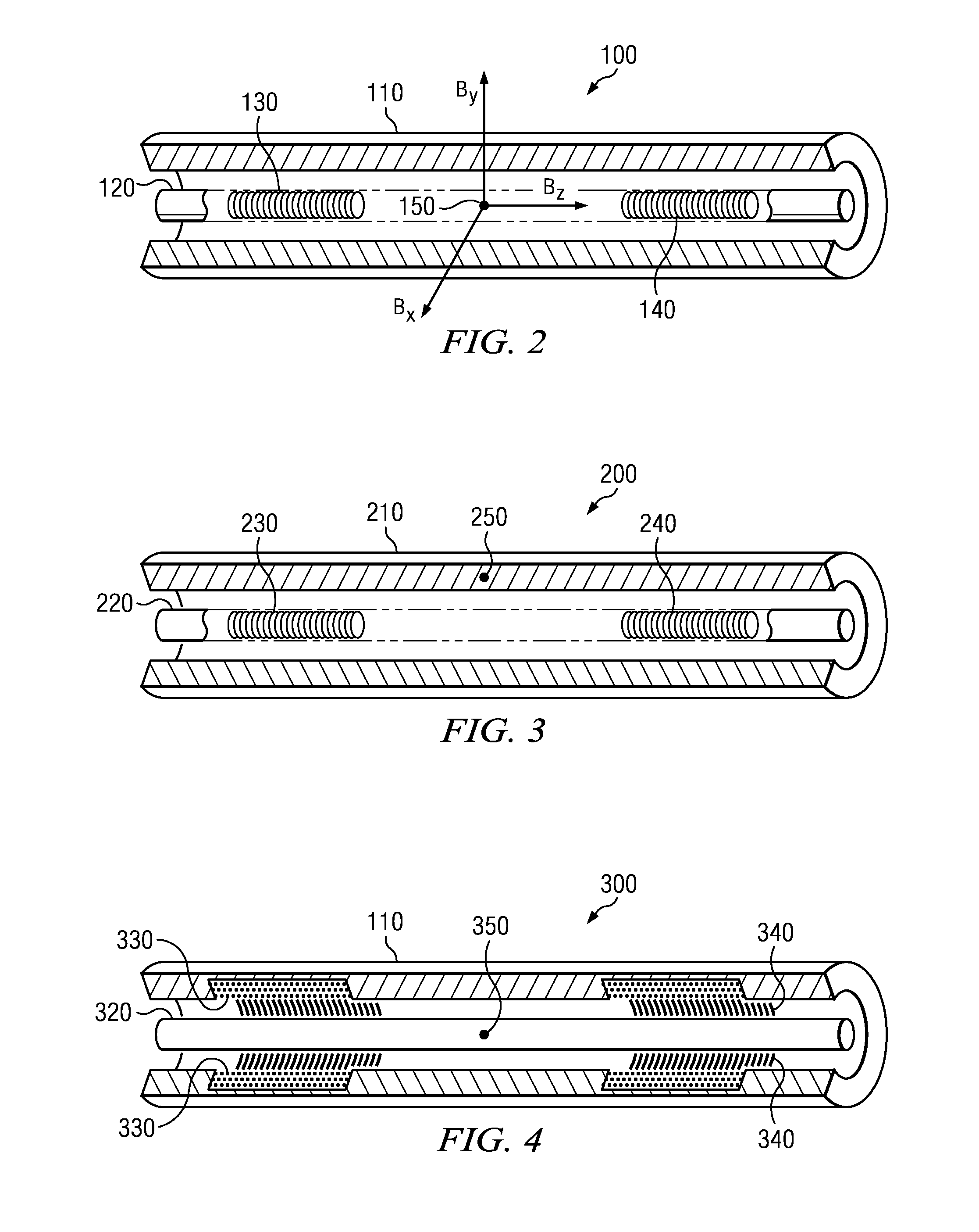
[0027]FIG. 1 depicts one example of a SAGD well twinning operation. A rig 10 is positioned over a subterranean oil or gas formation (e.g., a tar sands formation 16). The rig may include, for example, a derrick and a hoisting apparatus for lowering and raising a drill string 30 into an out of wellbore 40 (also referred to as the twin well and the drilling well). In the depicted embodiment drill string 30 includes a drill bit 32 and a magnetic ranging tool 100 deployed uphole of the drill bit 32. During a well twinning operation (e.g., as depicted) the magnetic ranging tool makes magnetic measurements while drilling which are used to compute the distance between the twin well 40 and the target well 50. The magnetic measurements may also be used to guide subsequent drilling of the twin well 40 with respect to the target well 50. The drill string 30 may further include a downhole drilling motor, a steering tool such as a rotary steerable tool or a bent sub, a downhole telemetry system, ...


PUM


Abstract

A downhole magnetic ranging tool includes first and second axially spaced magnetic sources deployed in a downhole tool body. The first and second magnetic sources have magnetic moments that axially opposed one another. A magnetic field sensor is deployed axially between the first and second magnetic sources. The tool may be utilized, for example, in subterranean well twinning, well intercept, and well avoidance operations to obtain a separation distance and dip angle between a drilling well and a target well.

Description

CROSS REFERENCE TO RELATED APPLICATIONS[0001]None.FIELD OF THE INVENTION[0002]Disclosed embodiments relate generally to subterranean well drilling operations and more particularly to an apparatus and method for making magnetic ranging measurements while drilling.BACKGROUND INFORMATION[0003]Heavy oil is commonly produced by first heating the heavy oil to reduce its viscosity. For example, steam assisted gravity drainage “SAGD” operations are commonly employed to produce heavy oil in tar sands formations. In such SAGD applications, twin horizontal wells having a vertical separation distance typically in the range from about 4 to about 20 meters are drilled. Steam is injected into the upper well to heat the tar sand. The heated heavy oil contained in the tar sand and condensed steam may then be produced from the lower well. The success of such heavy oil recovery techniques is often dependent upon producing precisely positioned twin wells having a predetermined relative spacing in the h...

Claims


Application Information

Patent Timeline
Patent Type & Authority Applications(United States)
IPC IPC(8): G01V3/08G01V3/38G06F19/00
CPCE21B47/02216G01V3/28E21B47/0228G01V3/08
Inventor ZHANG, JUN
Owner SCHLUMBERGER TECH CORP
Why Eureka
Try Eureka