SLC-MLC Wear Balancing

Active Publication Date: 2013-07-04
SANDISK TECH LLC
View PDF15 Cites 141 Cited by
  • Summary
  • Abstract
  • Description
  • Claims
  • Application Information

AI Technical Summary

Benefits of technology

[0005]Methods and systems are disclosed herein for balancing wear

Problems solved by technology

However, at times, the SLC portion wears out at a different time than the MLC portion.
However, it may be difficult to reallocate cells wit

Method used


Image

  • SLC-MLC Wear Balancing
  • SLC-MLC Wear Balancing
  • SLC-MLC Wear Balancing

Examples


Embodiment Construction

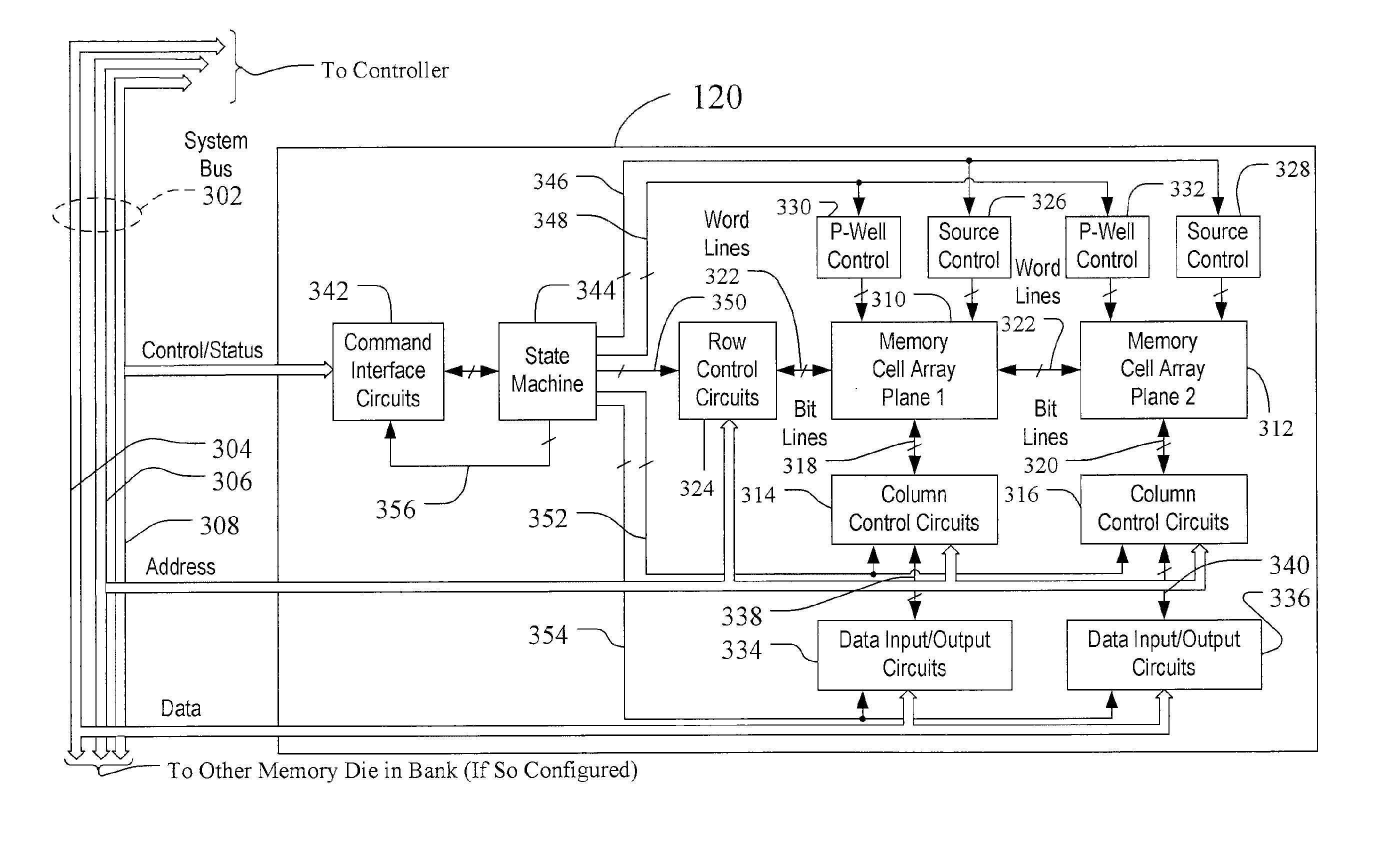
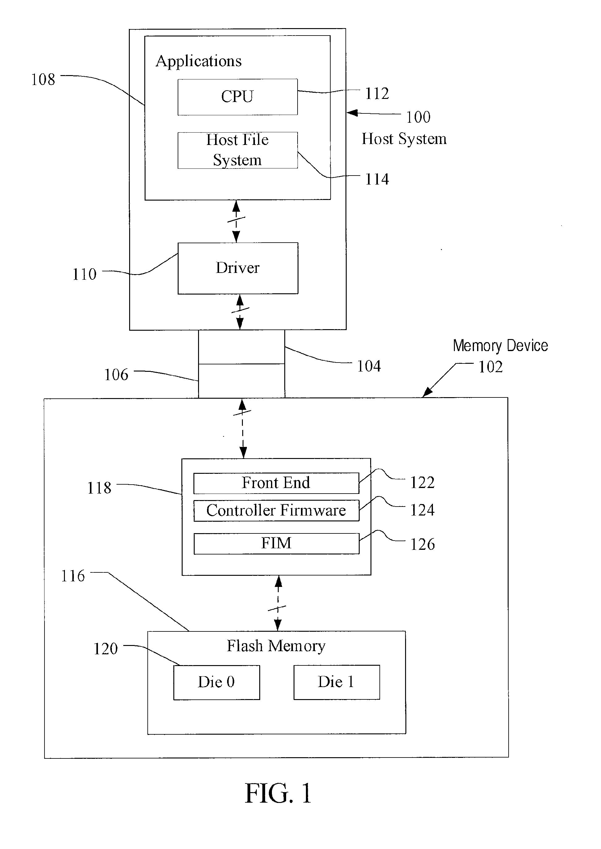
[0021]A flash memory device suitable for use in implementing aspects of the invention is shown in FIGS. 1-10. A host system 100 of FIG. 1 stores data into and retrieves data from a memory device 102. The memory device may be flash memory embedded within the host, such as in the form of a solid state disk (SSD) drive installed in a personal computer. Alternatively, the memory device 102 may be in the form of a card that is removably connected to the host through mating parts 104 and 106 of a mechanical and electrical connector as illustrated in FIG. 1. A flash memory configured for use as an internal or embedded SSD drive may look similar to the schematic of FIG. 1, with the primary difference being the location of the memory device 102 internal to the host. SSD drives may be in the form of discrete modules that are drop-in replacements for rotating magnetic disk drives.

[0022]The host system 100 of FIG. 1 may be viewed as having two major parts, insofar as the memory device 102 is co...


PUM


Abstract

A method and system for SLC-MLC Wear Balancing in a flash memory device is disclosed. The flash memory device includes a single level cell (SLC) portion and a multi-level cell (MLC) portion. The age of the SLC portion and the MLC portion may differ, leading potentially to one portion wearing out before the other. In order to avoid this, a controller is configured to receive an age indicator from one or both of the SLC portion and the MLC portion, determine, based on the age indicator, whether to modify operation of the SLC portion and/or the MLC portion, and in response to determining to modifying operation, modify the operation of the at least one of the SLC portion or the MLC portion. The modification of the operation may thus balance wear between the SLC and MLC portions, thereby potentially extending the life of the flash memory device.

Description

TECHNICAL FIELD[0001]This application relates generally to managing data in a memory system. More specifically, this application relates to balancing wear between single level cell memory and multi-level cell memory.BACKGROUND[0002]Non-volatile memory systems, such as flash memory devices, have been widely adopted for use in consumer products. Flash memory devices may be found in different forms, for example in the form of a portable memory card that can be carried between host devices or as a solid state disk (SSD) embedded in a host device. When writing data to a conventional flash memory device, a host typically writes data to, and reads data from, addresses within a logical address space of the memory system.[0003]The flash memory device includes an array of floating-gate memory cells. The memory cells may be operated to store more than two detectable levels of charge in each charge storage element or region, thereby to store more than one bit of data in each. This configuration...

Claims


Application Information

Patent Timeline
IPC IPC(8): G06F12/00
CPCG11C2211/5641G06F12/0246G11C16/349G06F2212/7211G06F2212/7202
Inventor CHEN, JIANGOROBETS, SERGEY ANATOLIEVICHSPROUSE, STEVEN
Owner SANDISK TECH LLC
Why Eureka
Try Eureka