Controlling Fresh Air and Exhaust Gas Flow in Turbocharged Internal Combustion Engine

a turbocharged internal combustion engine and fresh air technology, applied in the direction of electric control, machines/engines, mechanical equipment, etc., can solve the problems of additional problems in the operation of compressors, inability to generate charge pressure on the inlet side, etc., to reduce the charge pressure, reduce the air mass, and reduce the effect of power

Inactive Publication Date: 2013-07-11
FORD GLOBAL TECH LLC
View PDF10 Cites 8 Cited by
  • Summary
  • Abstract
  • Description
  • Claims
  • Application Information

AI Technical Summary

Benefits of technology

[0051]The first control element may also be adjusted such that a part of the exhaust gas is conducted through the recirculation line and the remaining part of the exhaust gas is conducted through the turbine. Since the second control element prevents a recirculation of exhaust gas when in the first position, in this case, the at least partially opened-up recirculation line functions, together with the bypass line, as a blow-off line via which exhaust gas is conducted past the turbine. The blow-off of exhaust gas leads to a reduction of the charge pressure on the inlet side, and thus to a decrease of the air mass introduced into the cylinder, and consequently to a decrease in power. Said measure, which can be carried out within the context of so-called de-rating, reduces the thermal loading of the internal combustion engine by reducing the power or the mean pressure. In said operating state, it is additionally the case that the blown-off exhaust gas is cooled in the cooling device, as a result of which the thermal loading of exhaust-gas aftertreatment systems provided in the exhaust-gas discharge system can be reduced. The blown-off exhaust gas may furthermore be utilized, after a cold start or in the warm-up phase, to introduce heat into the liquid-type cooling arrangement of the internal combustion engine, and thus into the internal combustion engine itself, by means of the cooling device which is operated with coolant. This advantageously assists the heating-up process of the internal combustion engine, as a result of which both the friction losses and also the emissions, in particular of unburned hydrocarbons, are noticeably reduced.
[0052]Said heating-up process can be further accelerated by virtue of the first control element being adjusted such that no exhaust gas whatsoever is conducted through the turbine, but rather all of the exhaust gas is conducted through the recirculation line. The amount of heat introduced into the internal combustion engine is thus increased or maximized, wherein the internal combustion engine operates as a naturally aspirated engine as a result of the deactivation of the exhaust-gas turbocharger.
[0053]In a second variation of the invention, the second control element is advantageously moved into the third position in which the at least one intake line and the bypass line are connected to one another and to the at least one cylinder. In said position of the second control element, it is possible, through corresponding adjustment of the first control element, for exhaust gas to be conducted back into the at least one cylinder, such that the charge air comprises not only fresh air but also recirculated exhaust gas. This is advantageous for reducing the nitrogen oxide emissions, in particular when the internal combustion engine has already been heated up or is hot. Here, the first control element may be adjusted in such a way that a part of the exhaust gas or all of the exhaust gas is conducted through the recirculation line. The latter is particularly advantageous for reducing the exhaust-gas back pressure and thus for improving efficiency at part load. If all of the exhaust gas is conducted through the turbine, it is possible during the course of a secondary air injection for fresh air to be injected into the exhaust-g...

Problems solved by technology

During the operation of an internal combustion engine with exhaust-gas turbocharging and with the simultaneous use of a high-pressure EGR arrangement, there is a basic conflict which consists in that the exhaust gas extracted upstream of the turbine for the purpose of recirculatio...

Method used


Image

  • Controlling Fresh Air and Exhaust Gas Flow in Turbocharged Internal Combustion Engine
  • Controlling Fresh Air and Exhaust Gas Flow in Turbocharged Internal Combustion Engine
  • Controlling Fresh Air and Exhaust Gas Flow in Turbocharged Internal Combustion Engine

Examples


Embodiment Construction

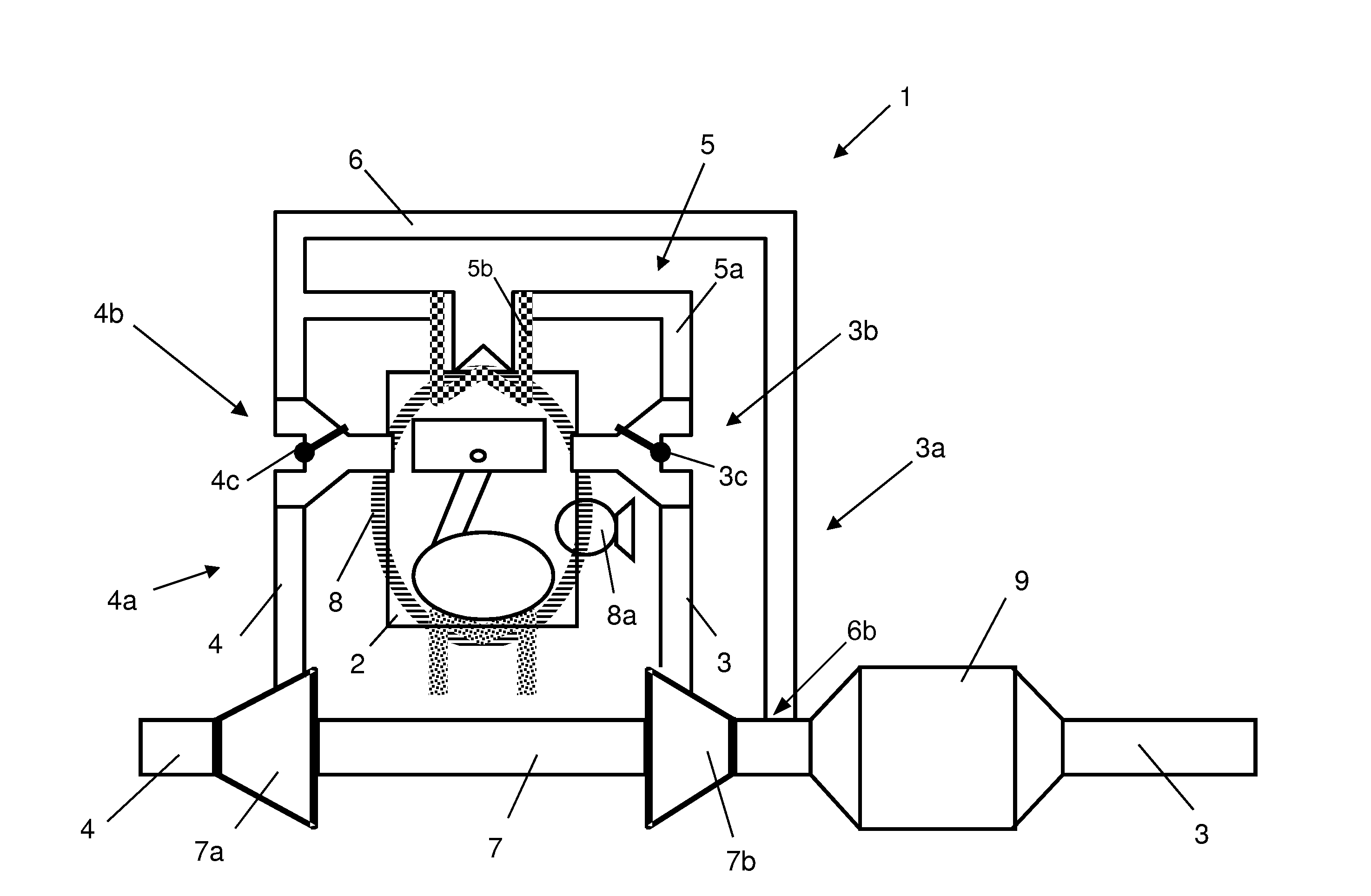
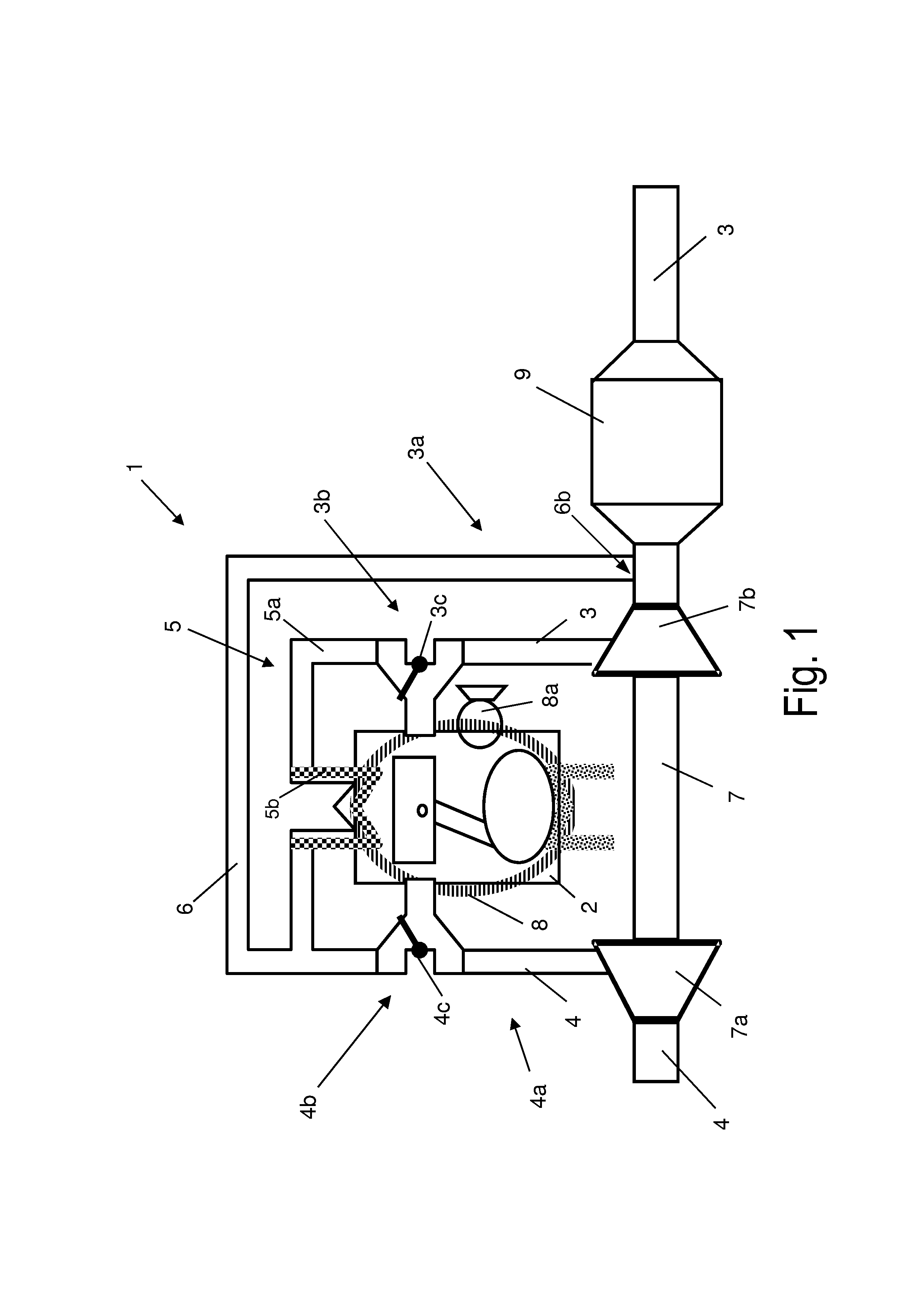
[0074]FIG. 1 schematically shows a first embodiment of the internal combustion engine 1 and, representatively, one cylinder 2. The fluid flows are not indicated. The internal combustion engine 1 has, at the outlet side, an exhaust line 3 for discharging the exhaust gases via an exhaust-gas discharge system 3a, and, at the inlet side, an intake line 4 for supplying charge air via an intake system 4a.

[0075]The internal combustion engine 1 is equipped, for supercharging, with an exhaust-gas turbocharger 7, the compressor 7a of which is arranged in the intake line 4 of the intake system 4a and the turbine 7b of which is arranged in the exhaust line 3 of the exhaust-gas discharge system 3a.

[0076]The internal combustion engine 1 is furthermore provided with a bypass line 6 for bypassing the cylinder 2, which bypass line branches off from the intake system 4a downstream of the compressor 7a so as to form an inlet-side junction 4b and opens into the exhaust-gas discharge system 3a again a...


PUM


Abstract

An internal combustion engine has a cylinder and an exhaust-gas turbocharger comprising a compressor arranged in an intake system and a turbine arranged in an exhaust-gas discharge system. Various lines are provided for conducting gases including 1) a bypass line branching off from the inlet system downstream of the compressor so as to form an inlet-side junction, and 2) a recirculation line branching off from the exhaust-gas discharge system upstream of the turbine so as to form an outlet-side junction which opens into the bypass line. A first control element at the outlet-side junction adjusts an exhaust-gas quantity conducted through the recirculation line. A second control element at the inlet-side junction has a first position that separates the bypass line from the cylinder and connects the intake line to the cylinder, and a second position that separates the intake line from the cylinder and connects the bypass line to the cylinder.

Description

CROSS REFERENCE TO RELATED APPLICATIONS[0001]This application claims priority to application 102012200111.5, filed in the German Patent and Trademark Office on Jan. 5, 2012, which is hereby incorporated by reference.STATEMENT REGARDING FEDERALLY SPONSORED RESEARCH[0002]Not Applicable.BACKGROUND OF THE INVENTION[0003]The invention relates to an internal combustion engine having at least one cylinder, at the outlet side at least one exhaust line for discharging the exhaust gases via an exhaust-gas discharge system, and at the inlet side at least one intake line for supplying charge air via an intake system, which internal combustion engine is equipped with[0004]at least one exhaust-gas turbocharger comprising a compressor arranged in the intake system and a turbine arranged in the exhaust-gas discharge system,[0005]a bypass line for bypassing the at least one cylinder, which bypass line branches off from the intake system downstream of the compressor so as to form an inlet-side juncti...

Claims


Application Information

Patent Timeline
IPC IPC(8): F02M25/07F02B47/08
CPCF02B47/08F02M25/07F02M25/0707F02M25/0726F02B37/183F02D41/068F02D41/0055F02B37/168Y02T10/144F02D21/08F02M26/02F02M26/05F02M26/22Y02T10/12
Inventor YACOUB, YASSER MOHAMED SAYED
Owner FORD GLOBAL TECH LLC
Why Eureka
Try Eureka