Gel reduction device and gel reduction method

a gel reduction device and gel reduction technology, applied in clay mixing equipment, rotary stirring mixers, transportation and packaging, etc., can solve the problems of high production rate and excessive pressure drop between upstream and downstream of the gel reduction device, and achieve the effect of reducing the gel in the compound and high productivity

Inactive Publication Date: 2013-07-11
KOBE STEEL LTD
View PDF11 Cites 16 Cited by
  • Summary
  • Abstract
  • Description
  • Claims
  • Application Information

AI Technical Summary

Benefits of technology

[0024]a step of constantly applying a pressure drop of 8.8 MPaG or higher to a compound containing gel at an intermediate position of the polymer flow duct in which the polymer flows, thereby reducing the gel in the compound.
[0025]According to the gel reduction device and gel reduction method of the present invention, a polymer kneaded compound containing few gels can be produced with high productivity.

Problems solved by technology

That is, also in the gel reduction device of patent literature 2, there is a possibility of producing an excessive pressure drop between upstream and downstream of the gel reduction device with a high production rate.

Method used


Image

  • Gel reduction device and gel reduction method
  • Gel reduction device and gel reduction method
  • Gel reduction device and gel reduction method

Examples


first embodiment

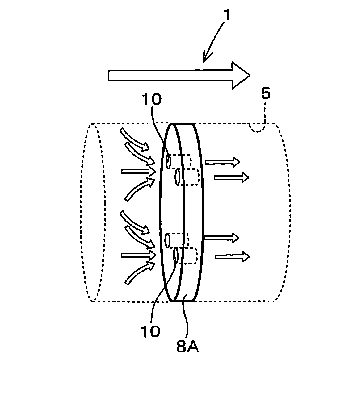
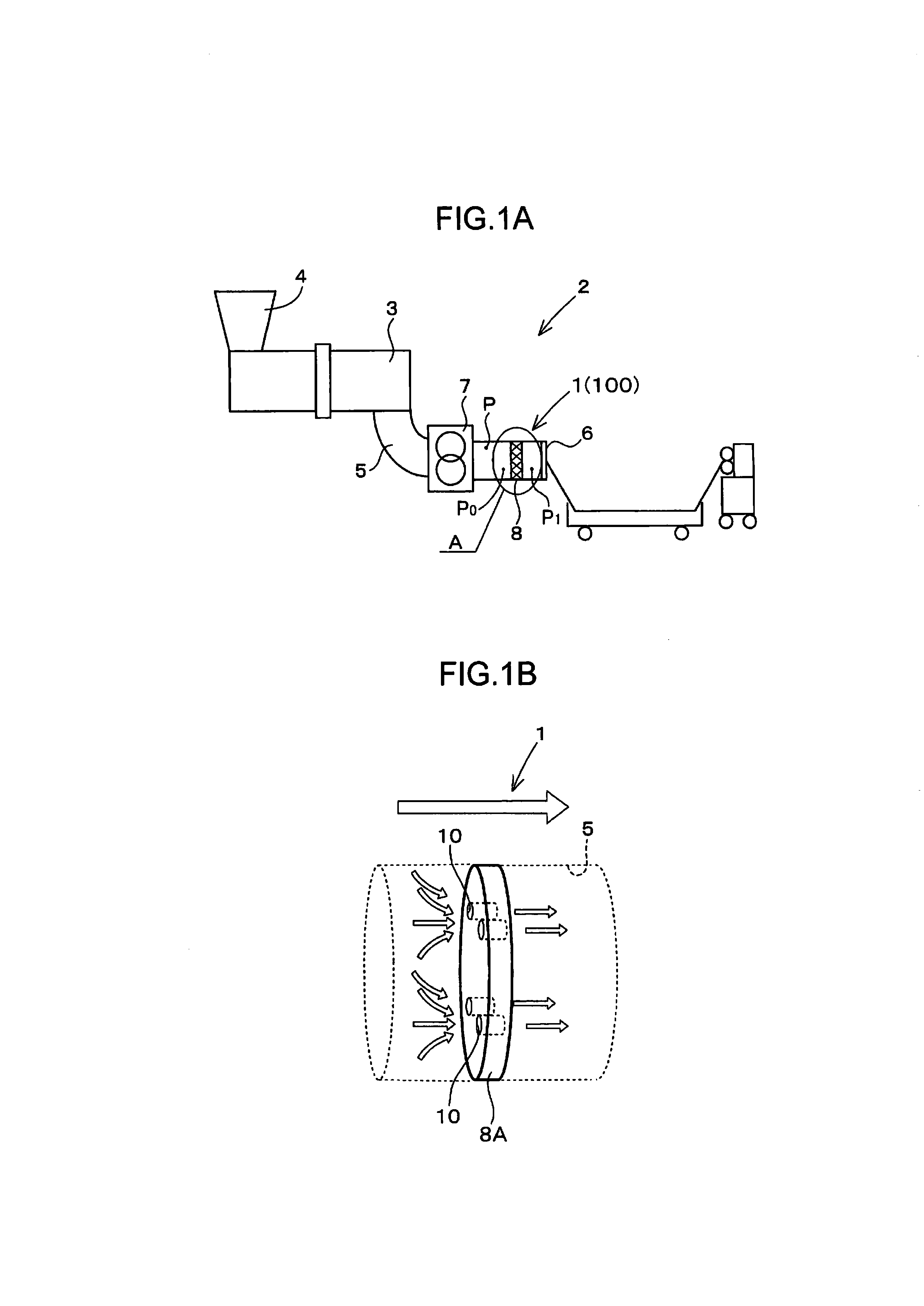
[0039]First, a mixing and extrusion equipment 2 in which a gel reduction device 1 is provided is briefly described prior to describing the gel reduction device 1 of the present invention.

[0040]FIG. 1A shows an example of the mixing and extrusion equipment 2 (an example of a continuous mixer) in which the gel reduction device 1 of the present invention is provided.

[0041]The mixing and extrusion equipment 2 of the shown example is a kneader for kneading a resin material by twin mixing rotors (not shown) inserted through a barrel 3. A hopper 4 capable of feeding materials into the barrel 3 is provided at one end (left end in FIG. 1A) of this barrel 3, and a polymer flow duct 5 for discharging the kneaded resin material to the outside of the kneader is provided at the other end.

[0042]A strand die 6 for extruding the polymer kneaded compound is provided at the leading end of this polymer flow duct 5, and a gear pump 7 for pressurizing the polymer kneaded compound to the strand die 6 is a...

second embodiment

[0062]Next, a gel reduction device 1 of a second embodiment is described.

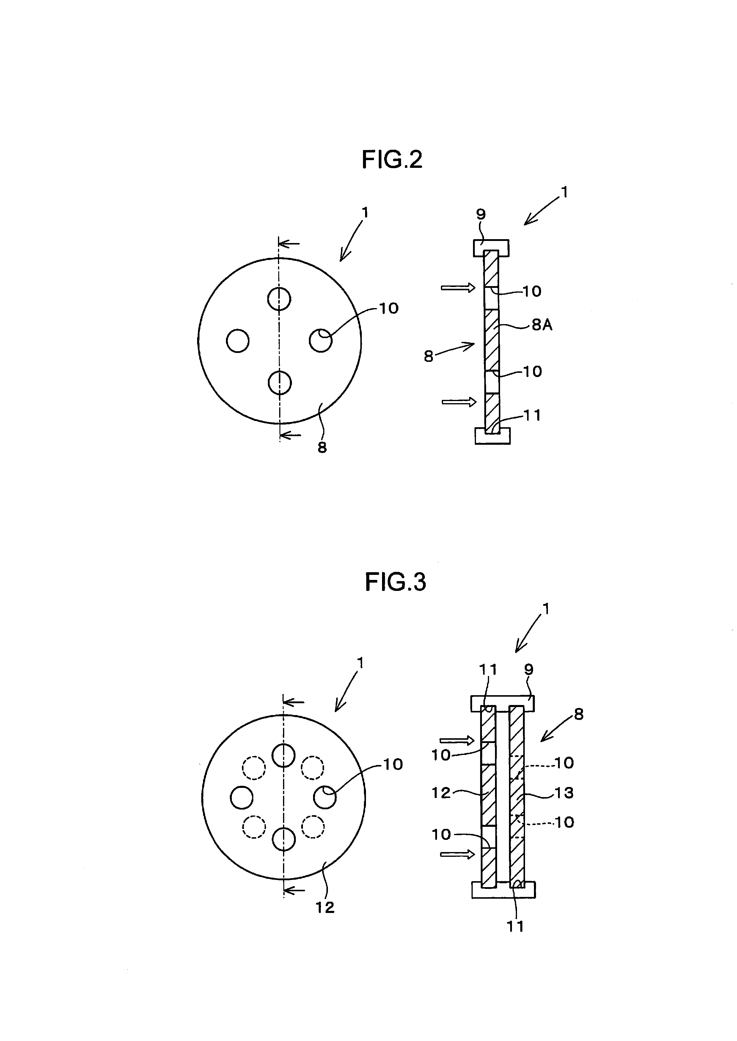
[0063]As shown in FIG. 3, a gel reduction mechanism 8 of the gel reduction device 1 of the second embodiment is so formed that a plurality of gel reduction members 8A of the first embodiment are arranged while being spaced apart in the laying direction of the polymer flow duct 5 (extending direction of the polymer flow duct 5 or axial center direction of the polymer flow duct 5). Specifically, this gel reduction device 1 includes a first gel reduction member 12 arranged at an upstream side and a second gel reduction member 13 arranged at a downstream side.

[0064]The first gel reduction member 12 is a disk-like member having the same thickness as the gel reduction member 8A of the first embodiment and includes four squeezing flow paths 10 penetrating from the upstream side toward the downstream side. The perforated positions and flow path cross-sectional areas of these squeezing flow paths 10 are also exactly the...

third embodiment

[0070]As shown in FIG. 4A, a gel reduction device 1 of a third embodiment includes a filter-like member 14, which is a circular metal plate formed with a multitude of passage pores, as a gel reduction mechanism 8.

[0071]This filter-like member 14 is a metal mesh formed by interweaving metal strands such that a mesh size of the passage pores is 180 μm or smaller and allows passage of foreign matters other than those having large sizes such as gel in a polymer kneaded compound. The thickness of this filter-like member 14 is very small as compared with the gel reduction mechanisms 8 of the first and second embodiments. Also in a shown example, the thickness of the gel reduction mechanism 8 of the third embodiment is about 1 / 10 of those of the gel reduction mechanisms 8 of the first and second embodiments.

[0072]The porous gel reduction mechanism 8 described above is formed with four squeezing flow paths 10 similar to the first and second embodiments. These squeezing flow paths 10 are for...


PUM

PropertyMeasurementUnit
widthaaaaaaaaaa
areaaaaaaaaaaa
mesh sizeaaaaaaaaaa

Abstract

A gel reduction device 1 of the present invention includes a gel reduction mechanism 8 provided in a polymer flow duct 5 in which a polymer kneaded compound flows and adapted to reduce gel present in the polymer kneaded compound. The gel reduction mechanism 8 includes at least one or more squeezing flow paths 10 having a flow path cross-sectional area smaller than the polymer flow duct 5, and a squeeze ratio S1/S2 of the squeezing flow paths 10 is set to be 25 to 180 so as to be able to generate an extensional flow in the kneaded compound flowing in the squeezing flow paths 10.

Description

TECHNICAL FIELD[0001]The present invention relates to a device and a method for reducing gel present in polymer.BACKGROUND ART[0002]In recent years, demands, which are to melt-blend different viscosity polymers and to produce binary or multi modal polymers, have been increased in order to meet functions of final product applications. A part of a high viscosity polymer or a high molecular component becomes gels, if dispersive mixing performances of polymer melting and mixing of mixers and extruders are not sufficient to perform complete homogeneity. Gels in such a compound may result in worse appearance and may degrade mechanical properties of final products. Accordingly, gel reduction devices have been provided for mixers and extruders.[0003]For example, a method and a device for reducing gel (removing gel) in a polymer kneaded compound using a filtration device including a filter made of a metal sintered body are proposed in patent literature 1. The filter used in this filtration d...

Claims


Application Information

Patent Timeline
Patent Type & Authority Applications(United States)
IPC IPC(8): B29B7/80B29C48/05B29C48/08B29C48/37B29C48/693B29C48/695B29C48/92
CPCB01F5/0688B01F5/0693B29B7/325B29B7/80B29C47/0004B29C47/0021B29C47/0898B29C47/70B29C47/8895B29C2947/92514B29C47/364B29C47/362B29C47/686B29C47/367B29C48/05B29C48/022B29C48/08B29C48/362B29C48/37B29C48/387B29C48/693B29C48/695B29C48/919B29C2948/92514B01F25/4523B01F25/4521B29B7/58
Inventor KURODA, YOSHINORIFUKUI, TSUGUSHIYAMAGUCHI, KAZUOUDA, TAKAYATAKAHASHI, KATSUNORIYAMADA, SAYAKA
Owner KOBE STEEL LTD
Why Eureka
Try Eureka