Mill and method of use

Active Publication Date: 2013-07-11
NUOVO PIGNONE TECH SRL
View PDF18 Cites 4 Cited by
  • Summary
  • Abstract
  • Description
  • Claims
  • Application Information

AI Technical Summary

Benefits of technology

[0010]According to still another exemplary embodiment, there is a method for plunge milling a workpiece. The method includes a step of rotating a cutting head while advancing the cutting head along a direction towards the workpiece; a stop of removing material from the workpiece with frontal teeth disposed on a frontal face of the cutting head; a step of bending a tool holder configured to lead the cutting head inside the workpiece; a step of stopping the advancing of the cutting head along the direction towards the workpiece when the cutting head has reached a predet

Problems solved by technology

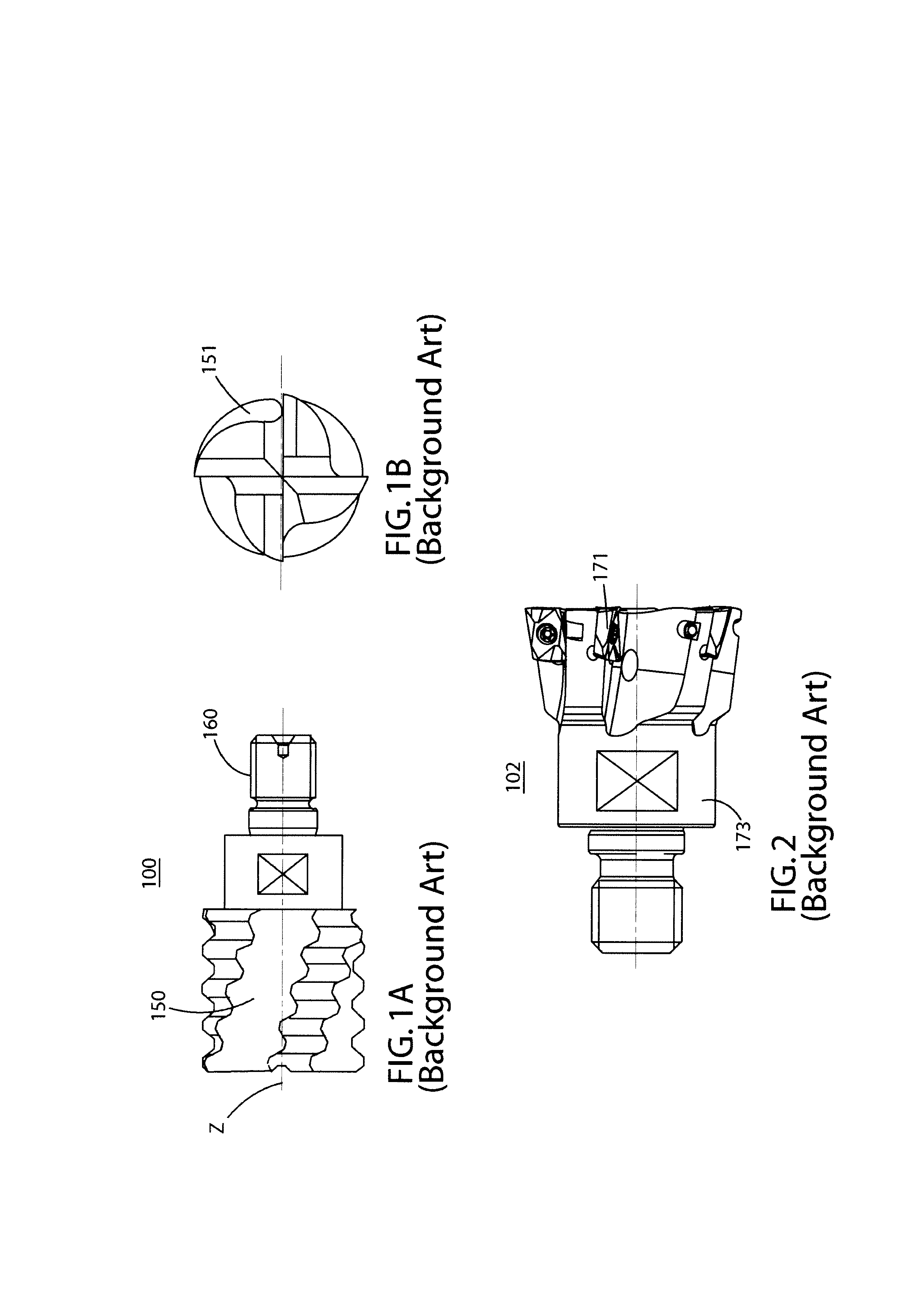
There are disadvantages, however, resulting from using the known mills 100 and 102.
This deflection can result in the blade having inaccurate geometries.
Th

Method used


Image

  • Mill and method of use
  • Mill and method of use
  • Mill and method of use

Examples


Embodiment Construction

[0032]The following description of exemplary embodiments refers to the accompanying drawings. The same reference characters in different drawings identify the same or similar elements. It is understood that the following detailed description does not limit the invention. Instead, the scope of the invention is defined by the appended claims.

[0033]Reference throughout the disclosure to “an exemplary embodiment,”“an embodiment,” or variations thereof means that a particular feature, structure, or characteristic described in connection with an embodiment is included in at least one embodiment of the subject matter disclosed. Thus, the use of the phrases “in an exemplary embodiment,”“in an embodiment,” or variations thereof in various places throughout the disclosure is not necessarily referring to the same embodiment. Further, the particular features, structures, or characteristics disclosed herein may be combined in any suitable manner in one or more embodiments.

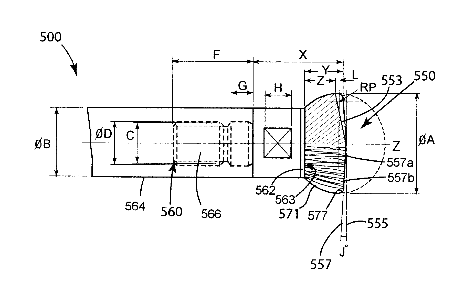
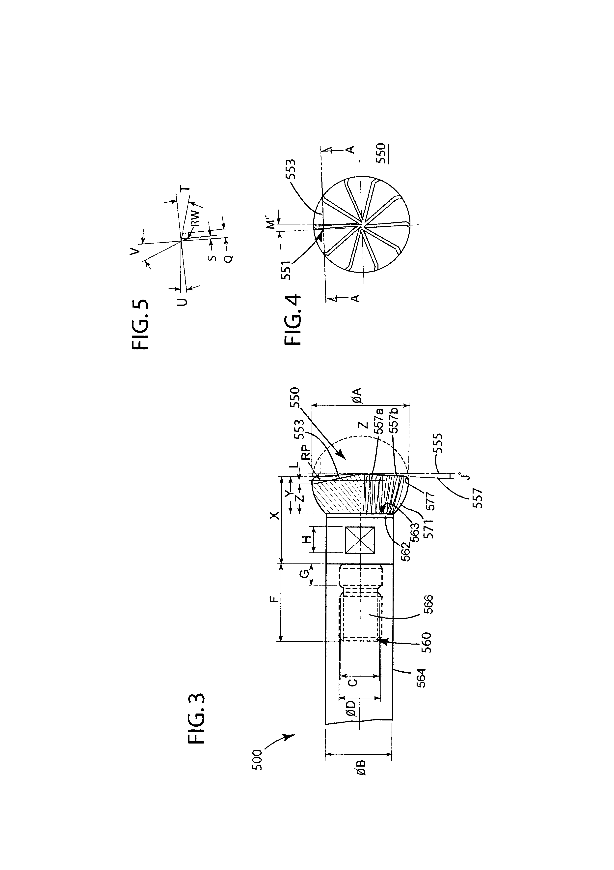
[0034]FIG. 3 is a parti...


PUM

PropertyMeasurementUnit
Fractionaaaaaaaaaa
Thicknessaaaaaaaaaa
Angleaaaaaaaaaa

Abstract

A method for plunge milling a workpiece. The method includes rotating a cutting head while advancing the cutting head along a direction towards the workpiece; removing material from the workpiece with frontal teeth disposed on a frontal face of the cutting head; bending a tool holder configured to lead the cutting head inside the workpiece; stopping the advancing of the cutting head along the direction towards the workpiece when the cutting head has reached a predetermined depth inside the workpiece; and retrieving while rotating the cutting head from the inside of the workpiece such that side teeth of the cutting head remove material from the inside of the workpiece due to the bending of the tool holder.

Description

CROSS REFERENCE TO RELATED APPLICATIONS[0001]This is a national stage application under 35 U.S.C. §371(c) of prior-filed, co-pending PCT patent application serial number PCT / EP2010 / 069978, filed on Dec. 16, 2010, which claims priority to Italian Patent Application Serial No. CO2009A000073, filed on Dec. 22, 2009, Italian Patent Application Serial No. CO2010A000033, filed on Jun. 8, 2010, and Italian Patent Application Serial No. CO2009A000039, tiled on Jul. 30, 2010, the entire contents of which are incorporated herein by reference.BACKGROUND OF THE INVENTION[0002]The disclosure is directed to a mill, such as a mill used to perform a Z-axis plunging operation, and a method of using the mill to perform the plunging operation.[0003]It is known to use a compressor in the oil and gas industry. For example, the compressor can be used to pressurize oil or gas flowing through the pipeline. It is also known to use an impeller blade with a relatively complex geometry in the compressor, to ac...

Claims


Application Information

Patent Timeline
IPC IPC(8): B23C3/00B23P15/34B23C5/02
CPCB23C3/18B23C5/10B23C2210/02B23C2210/084B23C2215/44Y10T409/303808B23C3/00B23C5/02B23P15/34Y10T407/1946Y10T409/303416B23C2220/56
Inventor CIGNI, EMANUELE
Owner NUOVO PIGNONE TECH SRL
Why Eureka
Try Eureka