Antenna and mobile terminal including the antenna
- Summary
- Abstract
- Description
- Claims
- Application Information
AI Technical Summary
Benefits of technology
Problems solved by technology
Method used
Image

Examples
case 8
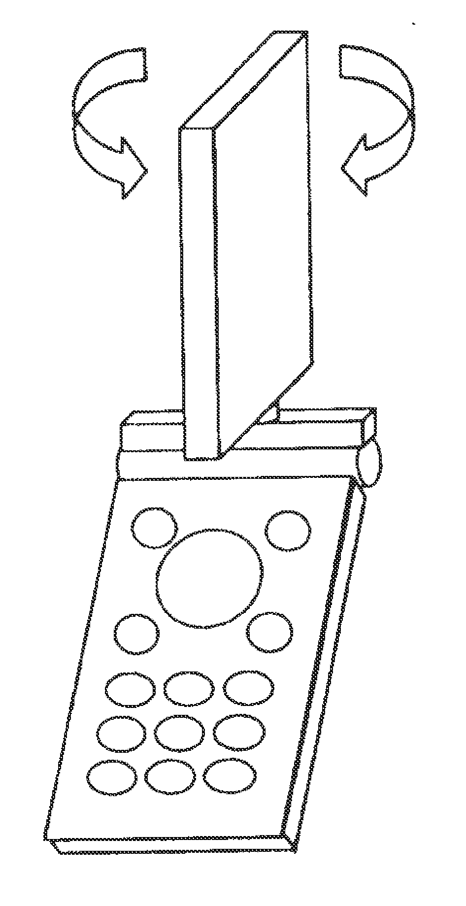
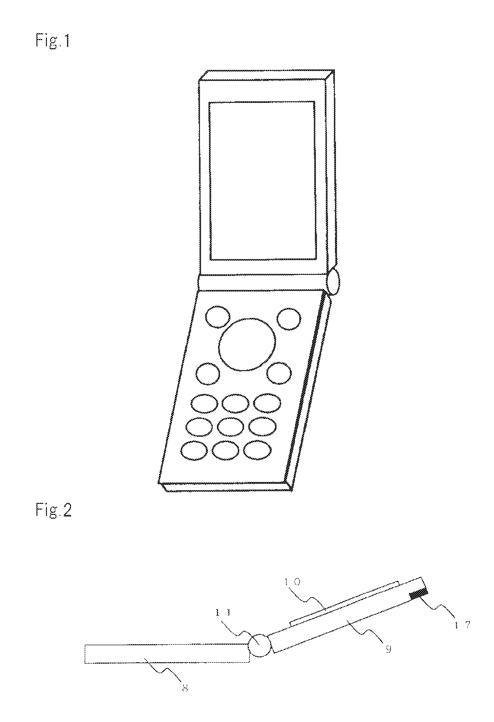
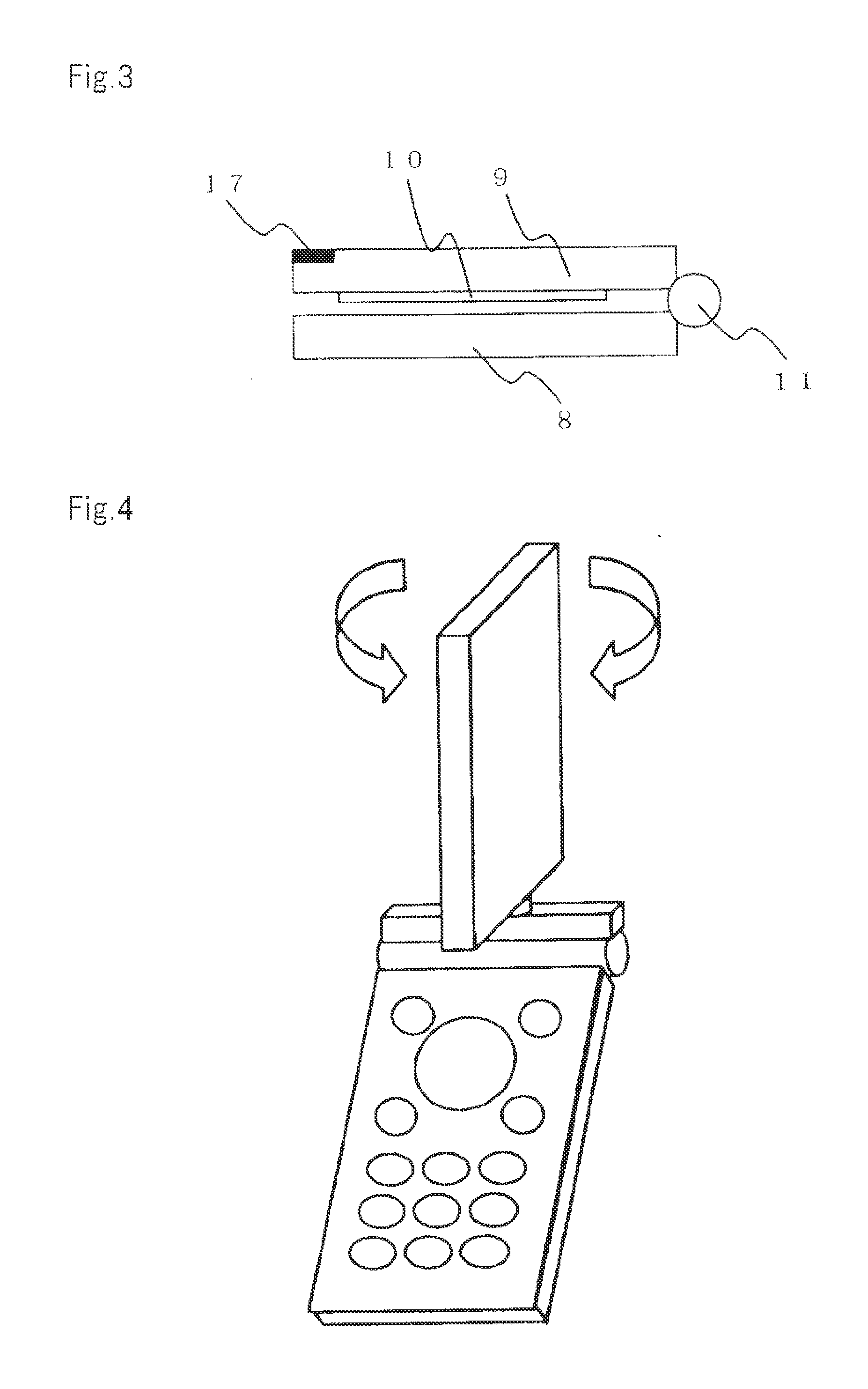
[0071]Operation side case 8 and display side case 9 having liquid crystal display unit 10 are connected by hinge 11. As shown in FIG. 8, display side case 9 is structured to be rotatable by rotary unit 12. This is one of the general configurations of the mobile terminal.
[0072]When the antenna according to the embodiment is located at the tip of display side case 9 of such a mobile terminal, antenna elements 1 and 2 are set in a shown positional relationship. Specifically, the antenna is housed in the case so that at the tip of display side case 9, the longitudinal direction of antenna elements 1 and 2 that are parallel to each other can be parallel to a direction orthogonal to the longitudinal direction of case 9.
[0073]FIG. 8 shows the folded state (closed state) of the mobile terminal shown in FIG. 7. Antenna element 1 is set at a position closest to operation side case 8 including many metals such as batteries or substrates, i.e., the position of large capacitive coupling. At this...
PUM
 Abstract
Description
Claims
Application Information
PatSnap Eureka turns technology decisions into work you can execute. Powered by our Innovation Knowledge Graph, it runs expert workflows across engineering, life sciences, materials and intellectual property. Get your review-ready output in minutes.


