Imaging apparatus, lens apparatus, imaging apparatus controlling method, lens apparatus controlling method, computer program, and imaging system

a technology of lens and control lens, applied in the field of automatic focus adjustment technique, can solve the problems of reduced responsiveness to af control, inability to set too small, and limited control resolution of focus lens position control, and achieve the effect of less degradation of performan

Active Publication Date: 2013-07-18
CANON KK
View PDF6 Cites 10 Cited by
  • Summary
  • Abstract
  • Description
  • Claims
  • Application Information

AI Technical Summary

Benefits of technology

[0019]The imaging apparatus of the present invention realizes control of an automatic focus adjustment operation with less degradation in performance in lens-exchange type imaging apparatuses while the influence of the change in image magnification is not noticeable on a screen.
[0020]In addition, even when the imaging apparatus of the present invention is combined with various types of interchangeable lenses, the imaging apparatus of the present invention realizes control of a focusing fluctuation of an image due to micro vibration of a focus lens in a case of a shallow depth of focus while ensuring an excellent responsiveness to AF control.

Problems solved by technology

Thus, the position control resolution of a focus lens is also limited.
However, the minimum value of each of the vibration amplitude amount and the shift amount of the vibration center is determined by the position control resolution of a focus lens corresponding to the drive resolution of a stepping motor, and thus, cannot be set too small.
Even if the vibration amplitude and the shift amount of the vibration center can be set small, the shift of the focus lens in the focusing direction becomes slow in AF control, resulting in a reduction in responsiveness to AF control.

Method used


Image

  • Imaging apparatus, lens apparatus, imaging apparatus controlling method, lens apparatus controlling method, computer program, and imaging system
  • Imaging apparatus, lens apparatus, imaging apparatus controlling method, lens apparatus controlling method, computer program, and imaging system
  • Imaging apparatus, lens apparatus, imaging apparatus controlling method, lens apparatus controlling method, computer program, and imaging system

Examples


first embodiment

Variant Example of First Embodiment

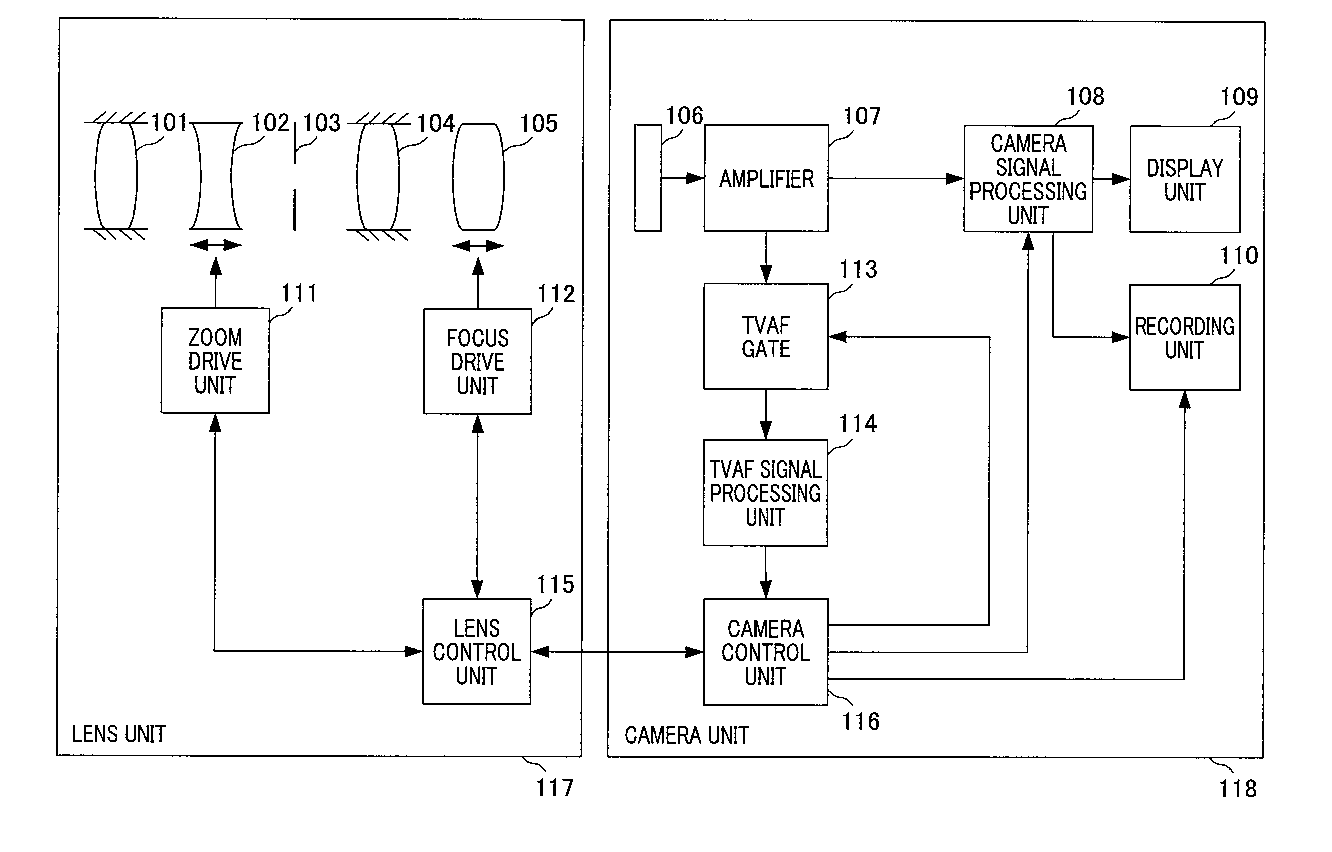
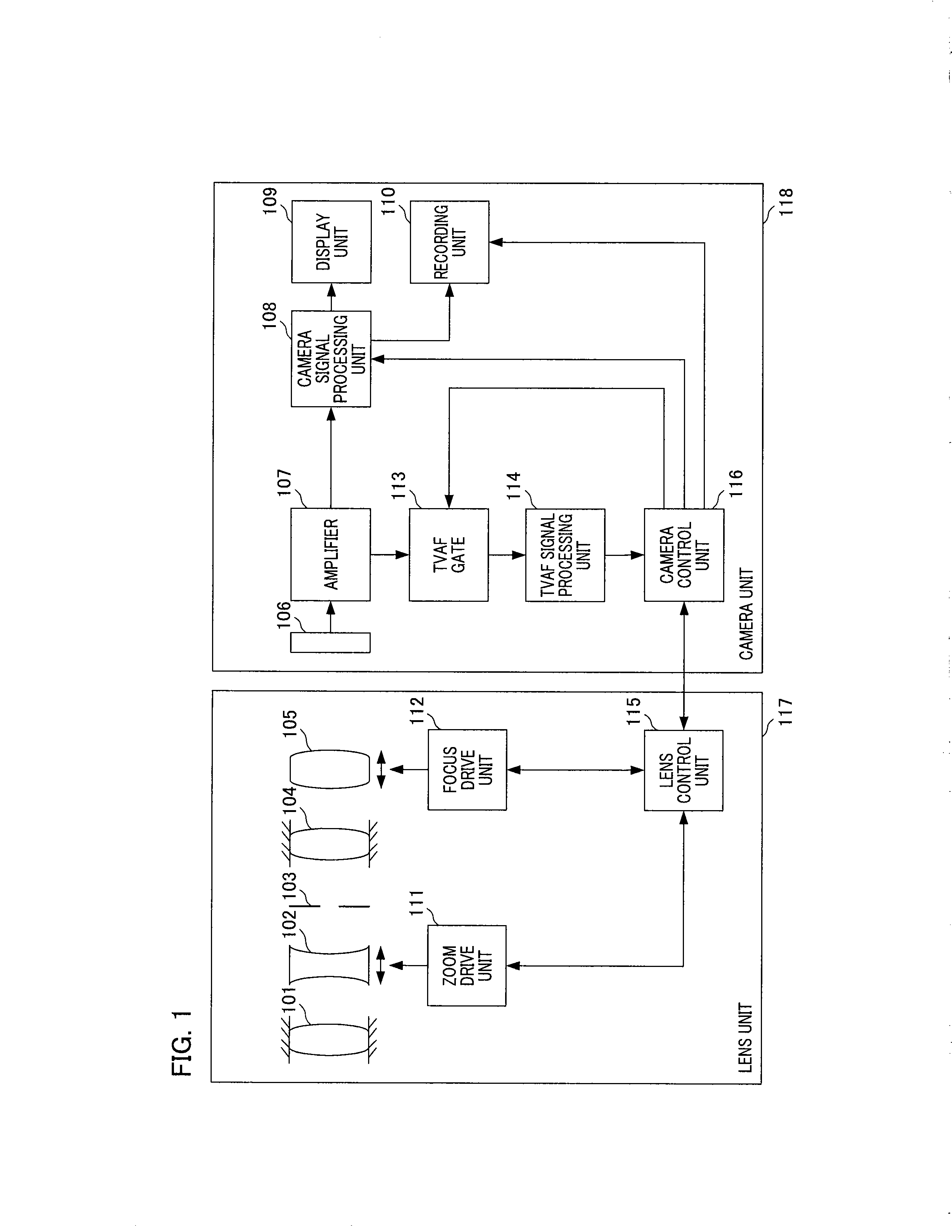
[0099]Next, a description will be given of a variant example of the first embodiment of the present invention. The configuration of the imaging apparatus of the variant example is the same as that of the first embodiment shown in FIG. 1. The same reference numerals as used in the first embodiment are used to denote the components of the variant example, and detailed description thereof will be omitted. The following description will be given of the differences from the first embodiment. Note that the methodology applied here in describing the variant of the first embodiment, in which detailed description of elements already described above is omitted, is also applied to other embodiments described below.

[0100]FIG. 11 is a flowchart illustrating control of the micro-driving operation among AF control performed by the camera control unit 116 according to the variant example of the first embodiment and corresponds to FIG. 4 of the first embodiment. Th...

second embodiment

Variant Example of Second Embodiment

[0197]In the second embodiment, a description has been given of the case where the camera body calculates the vibration amplitude amount, the center shift amount, and the depth of focus of the focus lens based on the lens unit-specific data received from the lens unit and switches the center shift scheme for use in AF control using the calculated information. However, the vibration amplitude amount and the center shift amount calculated by the camera body are values calculated in consideration of focus position sensitivity at the current vibration center based on an amount of defocus (image-plane amplitude amount and image-plane center shift amount) on an image capturing surface.

[0198]In other words, these values are not taken into account; the position of the focus lens after being shifted by the vibration amplitude amount and position sensitivity at the position of the focus lens after center shift. Thus, it may not be accurately determined whet...


PUM


Abstract

In a camera unit that is capable of attaching and detaching a lens unit, a camera control unit transmits a drive command for shifting a focus lens to a position corresponding to a focal point detected by use of an evaluation value for focus adjustment generated from an imaging signal by a TVAF signal processing unit to a lens control unit. The camera control unit acquires data indicating the amount of change in image magnification from the lens apparatus when performing center shift to thereby control the focus lens so as to suppress an out-of-focus blur of an image according to the image signal in response to the amount of change in image magnification relative to the shift amount of the focus lens in the vicinity of a focal point.

Description

BACKGROUND OF THE INVENTION[0001]1. Field of the Invention[0002]The present invention relates to an automatic focus adjustment technique suitable for use in an imaging apparatus such as a video camera having an interchangeable lens unit.[0003]2. Description of the Related Art[0004]In recent years, AF (auto focus) devices for video camera, that determine an AF evaluation value by detecting the sharpness of an image from an imaging signal and shift a focus lens to a position where the AF evaluation value becomes the highest to thereby perform focus adjustment, have been prevailing. Hereinafter, the above method is referred to as a “TVAF method”. As a TVAF evaluation value, the high frequency component level of a visible-image signal extracted by a band-pass filter for a predetermined frequency band is typically used. When an object is captured by the imaging system, a TVAF evaluation value increases as the focus lens is being focused and reaches a maximum at a focal point as shown in ...

Claims


Application Information

Patent Timeline
Patent Type & Authority Applications(United States)
IPC IPC(8): H04N5/232G02B7/38G03B13/36
CPCH04N5/23212G03B13/36G02B7/36H04N23/673
Inventor YASUDA, HITOSHITOMOSADA, TOSHIHIKO
Owner CANON KK
Why Eureka
Try Eureka