
CCD camera architecture and methods of manufacture

a technology of ccd camera and camera body, which is applied in the field of ccd camera architecture and methods of manufacture, can solve the problems of reducing the sensitivity of ccd camera, reducing the light energy reaching the observer, and reducing the distance between smaller bodies or bodies much farther from earth, so as to increase the dynamic range of ccd camera and snr. , the effect of increasing the dynamic rang

Inactive Publication Date: 2013-07-18
PAGE STEPHEN K +1
View PDF4 Cites 15 Cited by
  • Summary
  • Abstract
  • Description
  • Claims
  • Application Information

AI Technical Summary

Benefits of technology

The present invention aims to improve the dynamic range and signal-to-noise ratio (SNR) of a CCD camera by providing a better mounting. The patent describes a method for increasing the dynamic range of a CCD camera, making it more versatile and reliable. This invention results in high-quality photos with greater detail and greater depth of field, making it easier to capture and interpret the images.

Problems solved by technology

However, the sensitivity of CCD cameras decline dramatically in the near-IR regions, though they are the most cost-effective solution.
Smaller bodies or bodies much farther from earth are not as easily discerned and the reduction of light energy reaching the observer is often weak and, therefore, imperceivable to the standard imaging system.
In these situations, and many others, CCD cameras cannot faithfully reproduce images of low light intensity because of dark current, which degrade the image.
This current adds electronic “noise” to the CCD output, typically obscuring the signal generated from what small amount of light that might reach the sensor.

Method used


Image

  • CCD camera architecture and methods of manufacture
  • CCD camera architecture and methods of manufacture
  • CCD camera architecture and methods of manufacture

Examples


Embodiment Construction

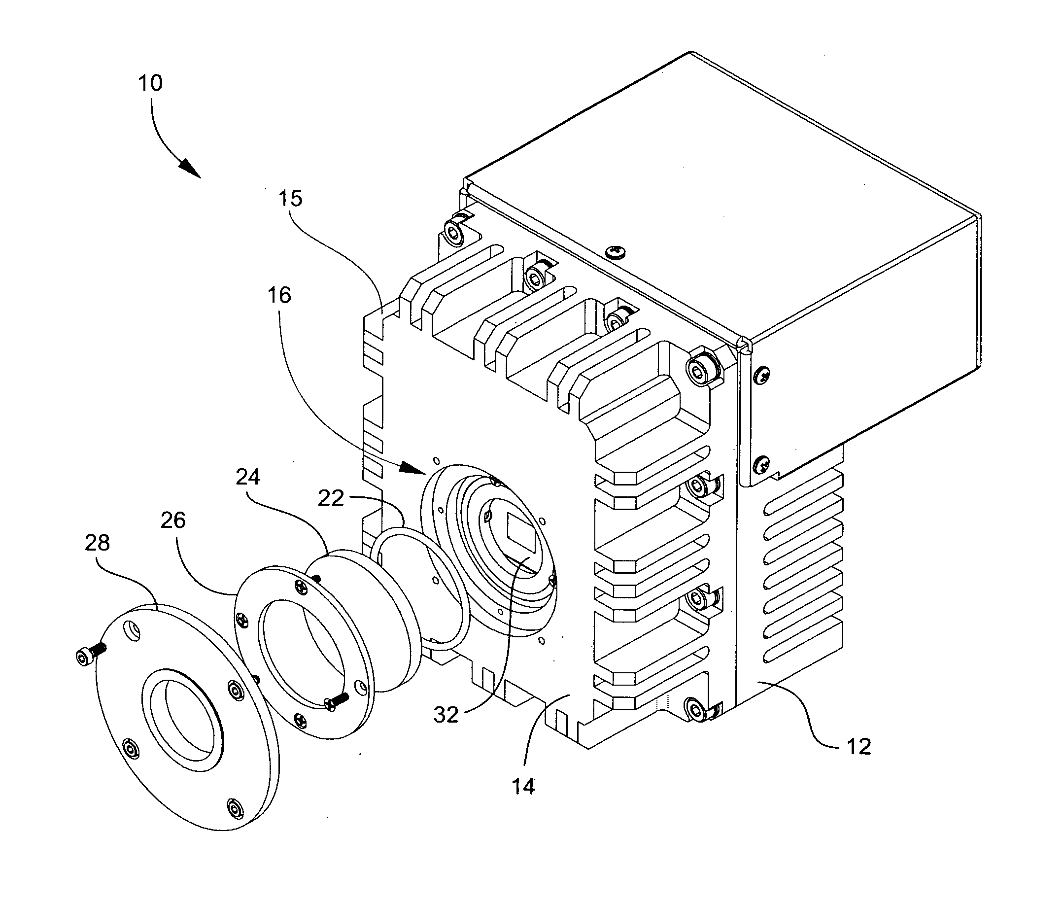
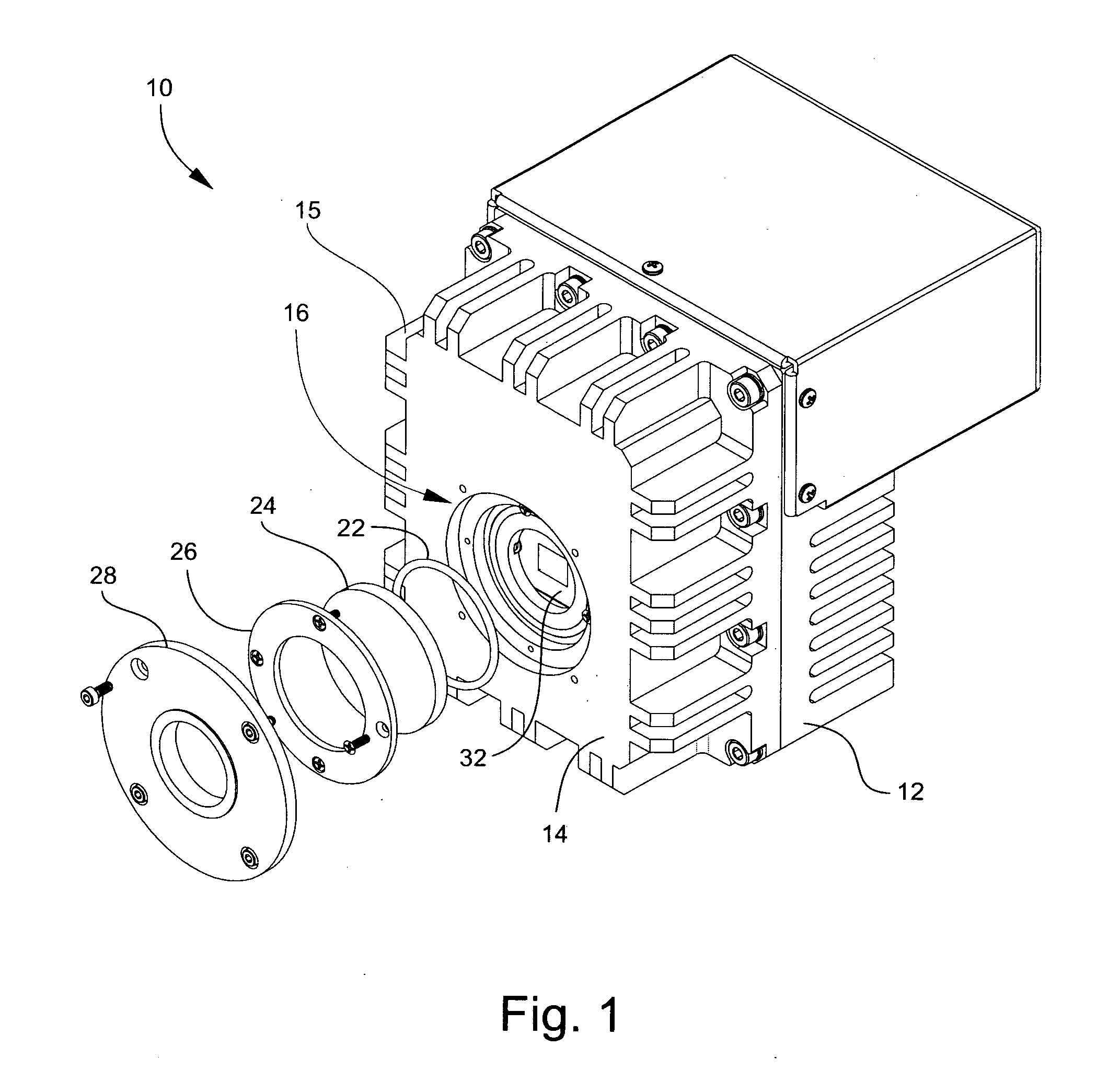
[0022]With reference to the drawings and in operation, the present invention provides an improved camera assembly 10 and method for increasing the dynamic range of CCD cameras used in low light applications.

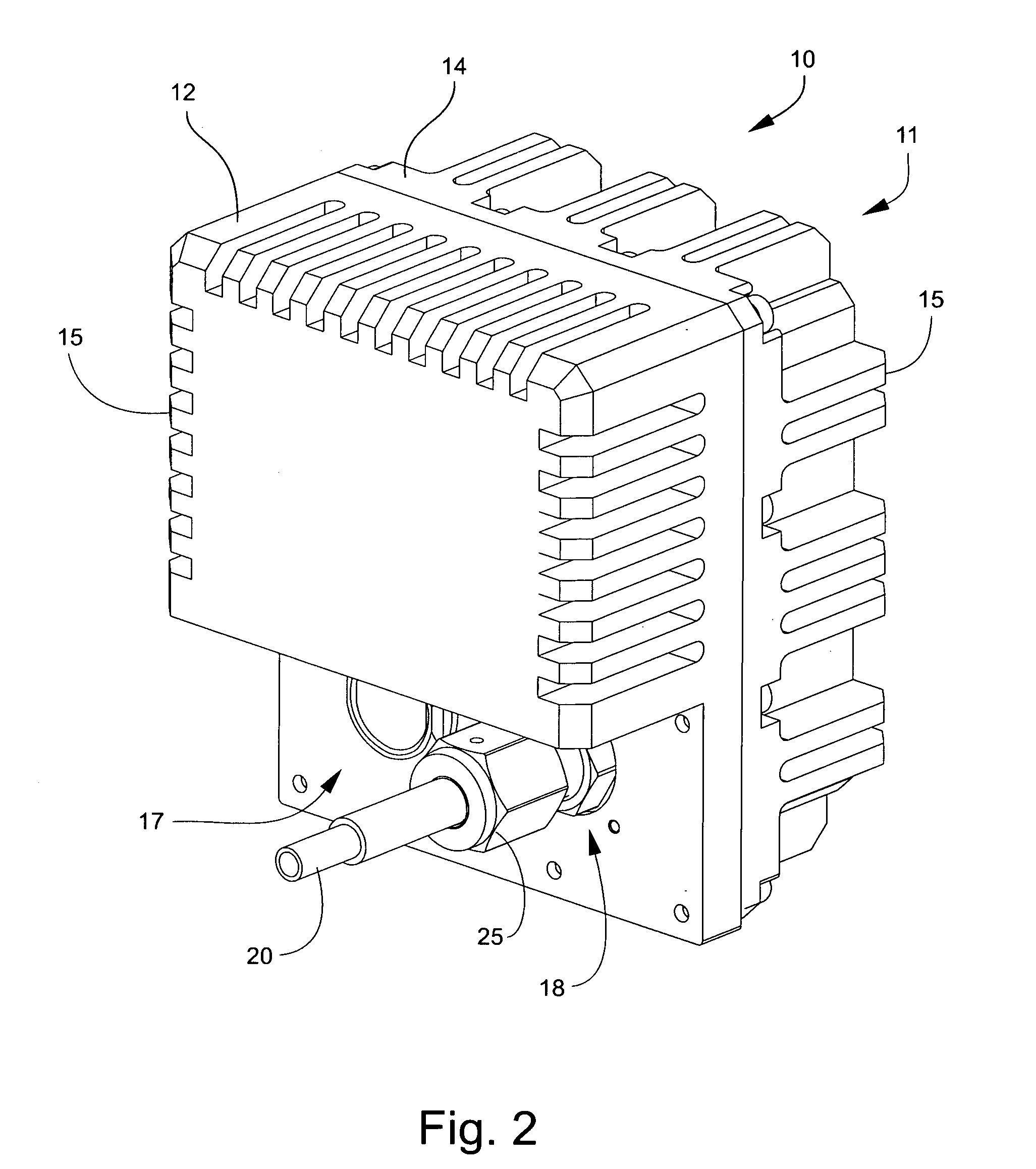
[0023]Typically, CCD cameras used in low light situations have a threaded orifice called a “C” mount located at the front of the camera case 11. There will be an electronics I / O port(s) is at the opposite end. If the camera case 11 needs to be evacuated, a vacuum port will be included, typically located on the front or back of the camera case 11. Typical electrical connections are either an IEEE1394 or a USB-2 port. Further, there may exist an auxiliary power jack for low voltage DC supply and / or an auxiliary jack for remote trigger.

[0024]The camera assembly 10 according to the present invention comprises a camera case 11 comprising an upper enclosure 12 and a lower enclosure 14 that defines an interior space sized to encompass a CCD camera 50. The upper and lower enclosures, 12 ...


PUM


Abstract

A charge-coupled device camera architecture for improving the dynamic range of the charge-coupled device camera having a charge-coupled device camera contained within a vacuum capable camera case and electrically attached to the outside of the camera case; a thermoelectric cooler thermally attached to a back side of the charge-coupled device camera and electrically attached to the outside of the camera case; a thermal redistribution block thermally attached to the thermoelectric cooler and further thermally attached to the camera case; a pressure measuring mechanism attached to an inside surface of the camera case and electrically connected to the outside of the camera case; a temperature measuring mechanism attached to a surface of the thermal redistribution block and electrically connected to the outside of the camera case; and a vacuum evacuation assembly having an indium lined copper pinch tube.

Description

FIELD OF THE INVENTION[0001]Charge-Coupled Device (CCD) cameras have many uses in scientific, industrial and consumer electronics markets. They have been used for portable and studio cameras, x-ray detectors, microscope cameras, and the like. While CCD cameras work well under many lighting scenarios, in the area of microscopy and astronomy a growing number of applications require the CCD camera to deliver a clean signal with a wide dynamic range in situations where the illumination is minimal.BACKGROUND[0002]In the area of scientific research and analysis, investigations through the microscope often involve the application of one or more dyes, or fluorochromes, to a sample cell (or other artifact) that are otherwise too small or lacking in sufficient natural contrast to be observed through the microscope. When exposed to narrow bands of energy, typically small segments of near UV to red visible light, the flourochromes release energy in the form of weak emissions in the visible ligh...

Claims


Application Information

Patent Timeline
IPC IPC(8): H04N5/225
CPCH04N5/2253H04N5/217H04N23/81H04N23/54
Inventor PAGE, STEPHEN K.COFFMAN, PHILLIP R.
Owner PAGE STEPHEN K
Learn More