
Hyperpolarization Apparatus And Method For Administration Of A Hyperpolarized Liquid Contrast Agent

a liquid contrast agent and apparatus technology, applied in the field of magnet resonance tomography, can solve the problems of large loss of hyperpolarization, limited magnetic field strength, and relatively complex methods known from the state of the ar

Active Publication Date: 2013-07-18
JOHANN WOLFGANG GOETHE UNIV FRANKFURT AM MAIN
View PDF1 Cites 1 Cited by
  • Summary
  • Abstract
  • Description
  • Claims
  • Application Information

AI Technical Summary

Benefits of technology

The invention relates to a device that uses DNP for polymerization of a contrast agent to be administered to a living being for MRT imaging. The device includes an MW resonator and a separate MRT device. The MW resonator is positioned in the same bore as the MRT device and is used to polarize the contrast agent using DNP. The polarized contrast agent is then immediately administered to the living being. This setup eliminates the need for separate magnets and coordination between hyperpolarization and MRT imaging. Additionally, the device includes a smaller conduit between the MW resonator and the patient, which allows for a longer residence time in the resonator and a shorter transport between the resonator and the patient. The MW resonator can be easily tuned to a desired resonance frequency using an iris. The technical effects of the invention are improved polarization efficiency, reduced transportation time, and improved image quality.

Problems solved by technology

However, there are technical limits to the strength of the magnetic field; typically, in state-of-the-art MRT devices, it is 1.5 T. With magnetic field strengths of more than 3.0 T, the patients can be moved into the magnet very slowly only, in order to minimize induced eddy currents, for example in the brain of the patient.
Then, the problem occurs that a substantial part of the hyperpolarization is lost due to relaxation processes upon transport.
Furthermore, the method known from the state of the art is relatively complex.

Method used


Image

  • Hyperpolarization Apparatus And Method For Administration Of A Hyperpolarized Liquid Contrast Agent
  • Hyperpolarization Apparatus And Method For Administration Of A Hyperpolarized Liquid Contrast Agent
  • Hyperpolarization Apparatus And Method For Administration Of A Hyperpolarized Liquid Contrast Agent

Examples


Embodiment Construction

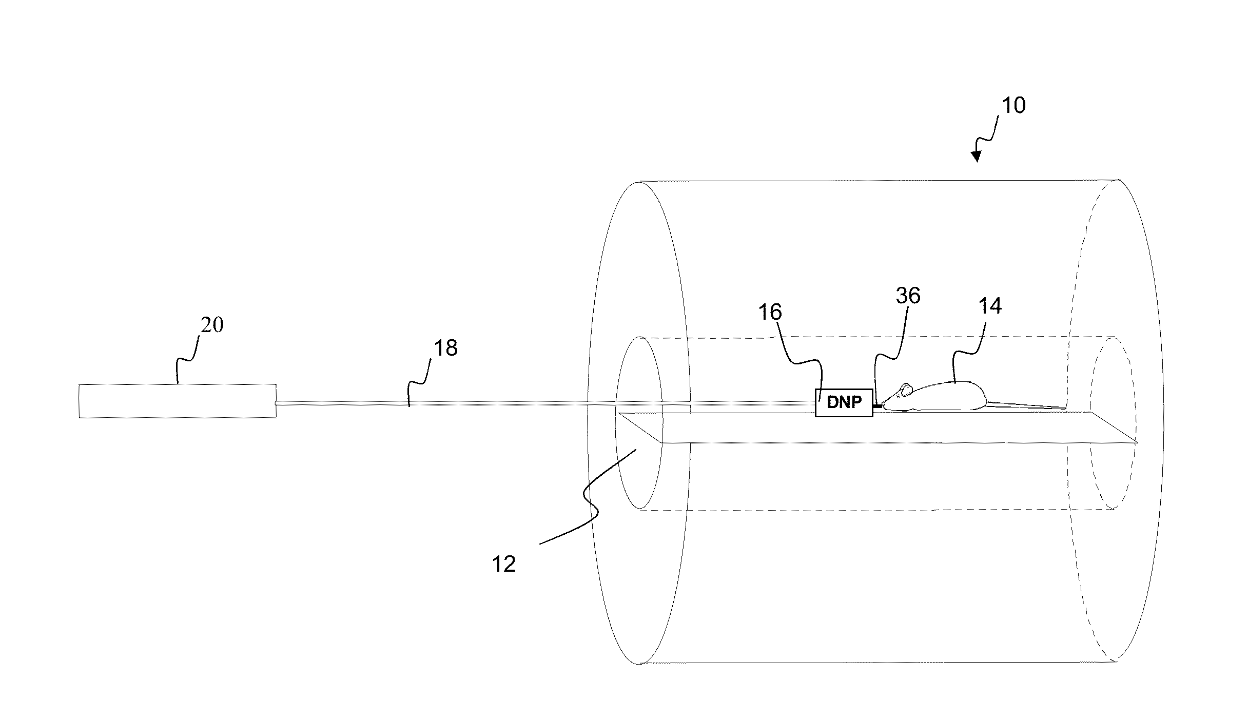
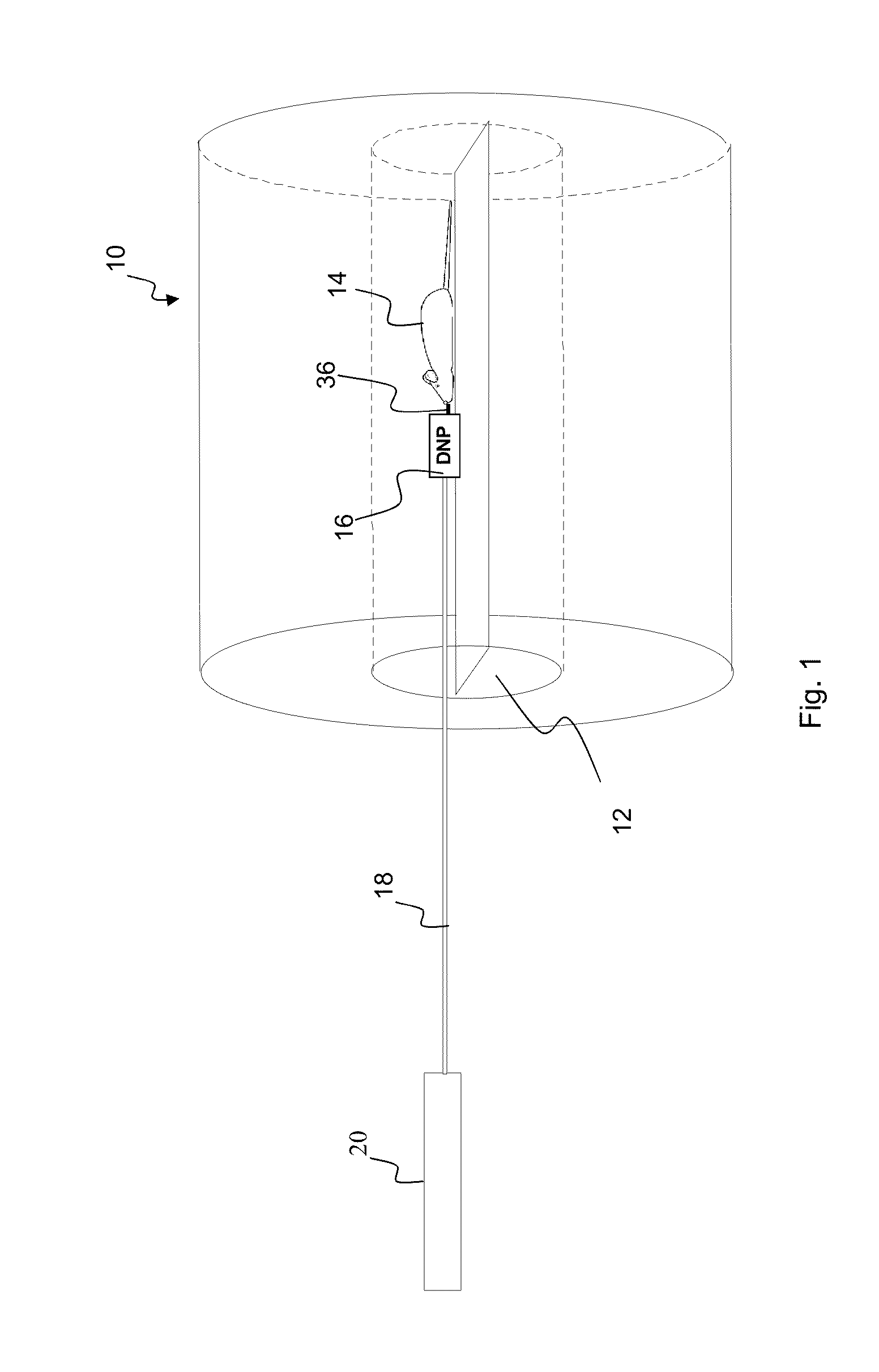
[0044]In FIG. 1, a magnet 10 of a MRT device is represented schematically. The magnet 10 has a bore 12 in which a static magnetic field with a strength of 1.49552 T is generated. Furthermore, in the MRT device, as customary, means for generating a high-frequency field for the resonant excitation of nuclear spins as well as means for generating a magnetic gradient field for imaging are provided, which, however, are not shown in the figure.

[0045]As further shown in FIG. 1, a living being to be examined 14, a mouse in the example shown, is located in the bore 12 of the magnet 10. The apparatus and the method of the invention, however, are likewise and particularly usable for applications in human medicine.

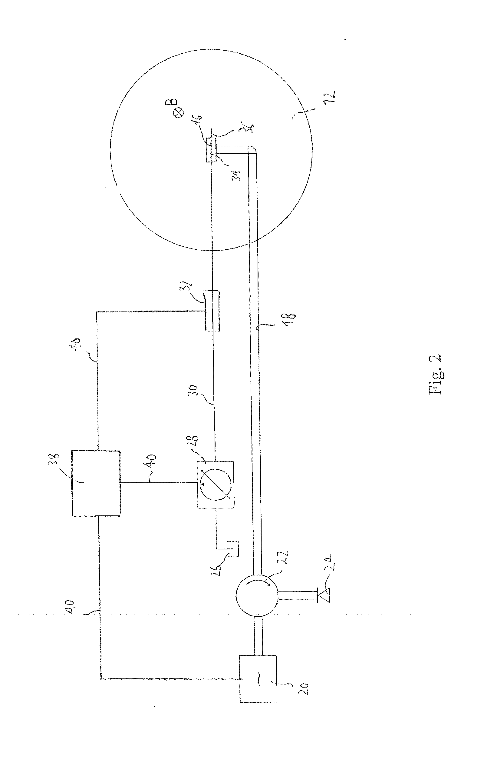
[0046]Furthermore, a MW resonator 16, which is connected with a microwave source 20 via a waveguide 18, is located in the bore 12 of the magnet 10. In the embodiment shown, the microwave source 20 is suitable for generating microwaves with frequencies in a range from 41 GHz to 43 GHz....


PUM


Abstract

A hyperpolarized liquid contrast agent is for use in a MRT device. The liquid contrast agent passes through a conduit of a MW resonator in the magnetic field of the MRT device. A microwave with a frequency of at least 40 GHz couples into the MW resonator for polarizing the liquid contrast agent upon passage through the conduit in the MW resonator using DNP. The contrast agent is polarized in a continuous passage in the MW resonator and administered immediately. A MW mode is formed in the MW resonator which has an antinode in the magnetic field strength and a node in the electric field strength. The power of the introduced microwave and coupling of the microwave into the resonator are adjusted such that in the area of the line, an amplitude of the MW magnetic field strength B1≧1.5·10−2 Ts 1 / T1,e results, wherein T1,e is the relaxation time of the DNP-active electrons.

Description

[0001]This application is a continuation of Patent Cooperation Treaty Patent Application PCT / EP2011 / 003125, filed Jun. 24, 2011, which in turn claims priority from German Patent Application 10 2010 017 568.4, filed Jun. 24, 2010, which are incorporated herein by reference.FIELD OF THE INVENTION[0002]The present invention lies in the field of magnet resonance tomography (MRT). In particular, it relates to an apparatus for hyperpolarization of a liquid NMR contrast agent and a method for administration of a hyperpolarized liquid contrast agent.BACKGROUND[0003]Magnet resonance tomography (MRT) is an imaging method, which is above all used in medical diagnostics for representing structures and functions of tissue and organs in the body. MRT is based on the principles of nuclear magnetic resonance NMR spectroscopy. For this method, the tissue to be examined is located in a strong static magnetic field, in which the spins of atomic nuclei in the examined tissue are aligned, which results ...

Claims


Application Information

Patent Timeline
IPC IPC(8): A61B5/055
CPCA61B5/055G01N24/12G01R33/62G01R33/5601G01R33/282
Inventor KRUMMENACKER, JANPRISNER, THOMASDENYSENKOV, VASYLSCHREIBER, LAURAMUNNEMANN, KERSTIN
Owner JOHANN WOLFGANG GOETHE UNIV FRANKFURT AM MAIN
Learn More