Multiple Dose Syringe and Method

a syringe and multi-dosage technology, applied in the field of multi-dosage syringe and method, can solve the problems of inaccurate dosage metering, difficult control, and ineffective dispensing of multiple doses of substances

Active Publication Date: 2013-07-18
DR PY INST LLC
View PDF4 Cites 31 Cited by
  • Summary
  • Abstract
  • Description
  • Claims
  • Application Information

AI Technical Summary

Benefits of technology

[0038]One advantage of the present invention is that the syringe or other device can effectively dispense multiple doses of a substance, such as medicaments, pharmaceuticals, vaccines, liquid nutrition products, supplements, and any of numerous other products that are currently known, or that later become known. Another advantage is that the substance to be dispensed is sealed within the storage chamber until it is dispensed, and therefore the substance can be maintained sterile, aseptic and / or contamination free within the storage chamber throughout the dispensing of multiple doses to different patients. The outlet valve prevents germs, bacteria or other contaminants at, for example, the needle or Luer connection, from traveling into the body of the syringe or storage chamber.

Problems solved by technology

One of the drawbacks of known syringes is that they are not as effective as desired for dispensing multiple doses of substances, such as medicaments, pharmaceuticals, vaccines, liquid nutrition products, supplements, or other products.
Other syringes that are not prefilled have significant drawbacks if used to dispense multiple doses.
Dosage metering can be inaccurate and difficult to control.
Thus, although a Luer-connection allows a needle to be discarded after single patient use and replaced with a fresh needle, the substance in the syringe body nevertheless can become contaminated during or between dispensing multiple doses.
This, in turn, can lead to the spread of germs, bacteria or other contaminants from one patient to another and give rise to harmful results.

Method used


Image

  • Multiple Dose Syringe and Method
  • Multiple Dose Syringe and Method
  • Multiple Dose Syringe and Method

Examples


Embodiment Construction

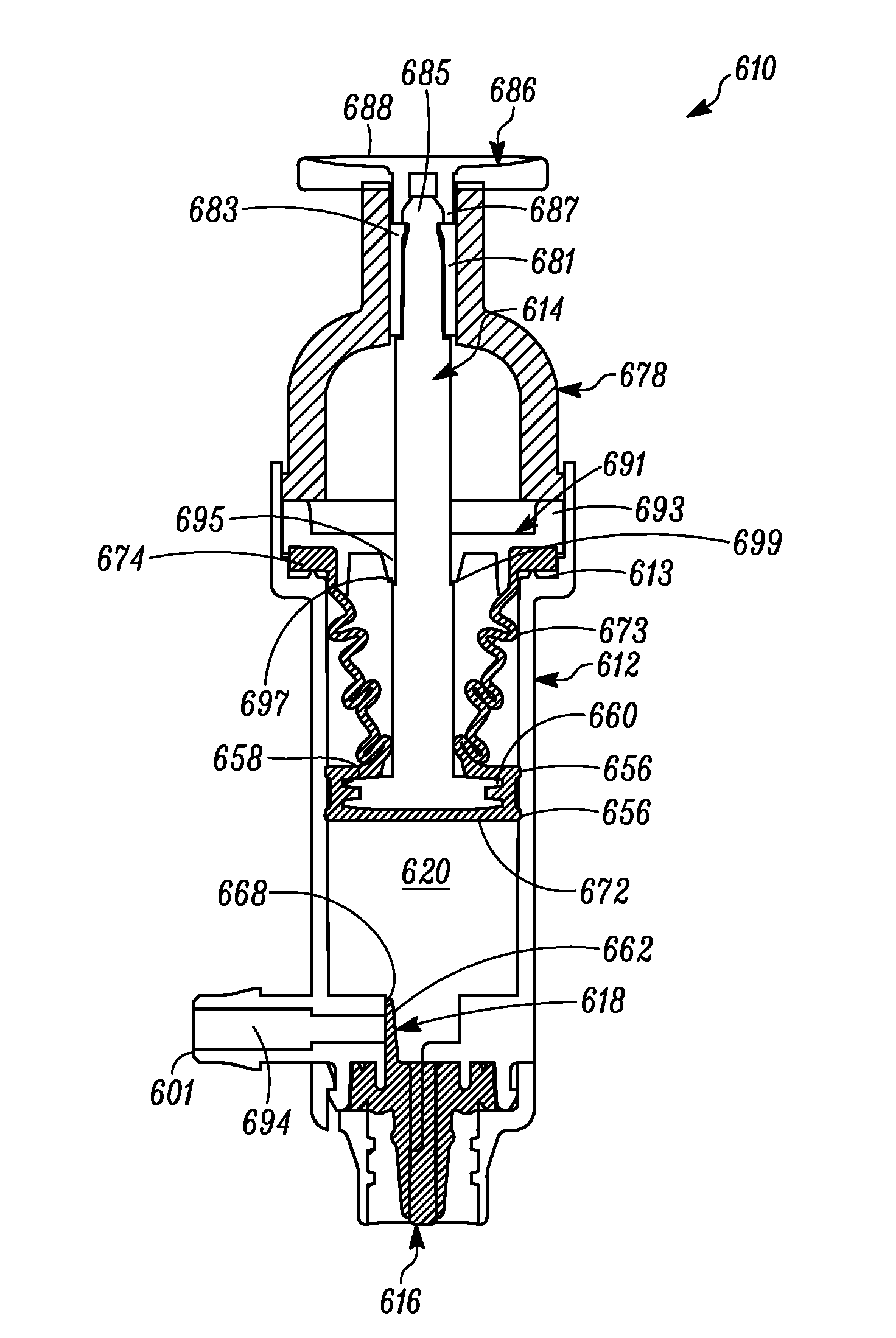
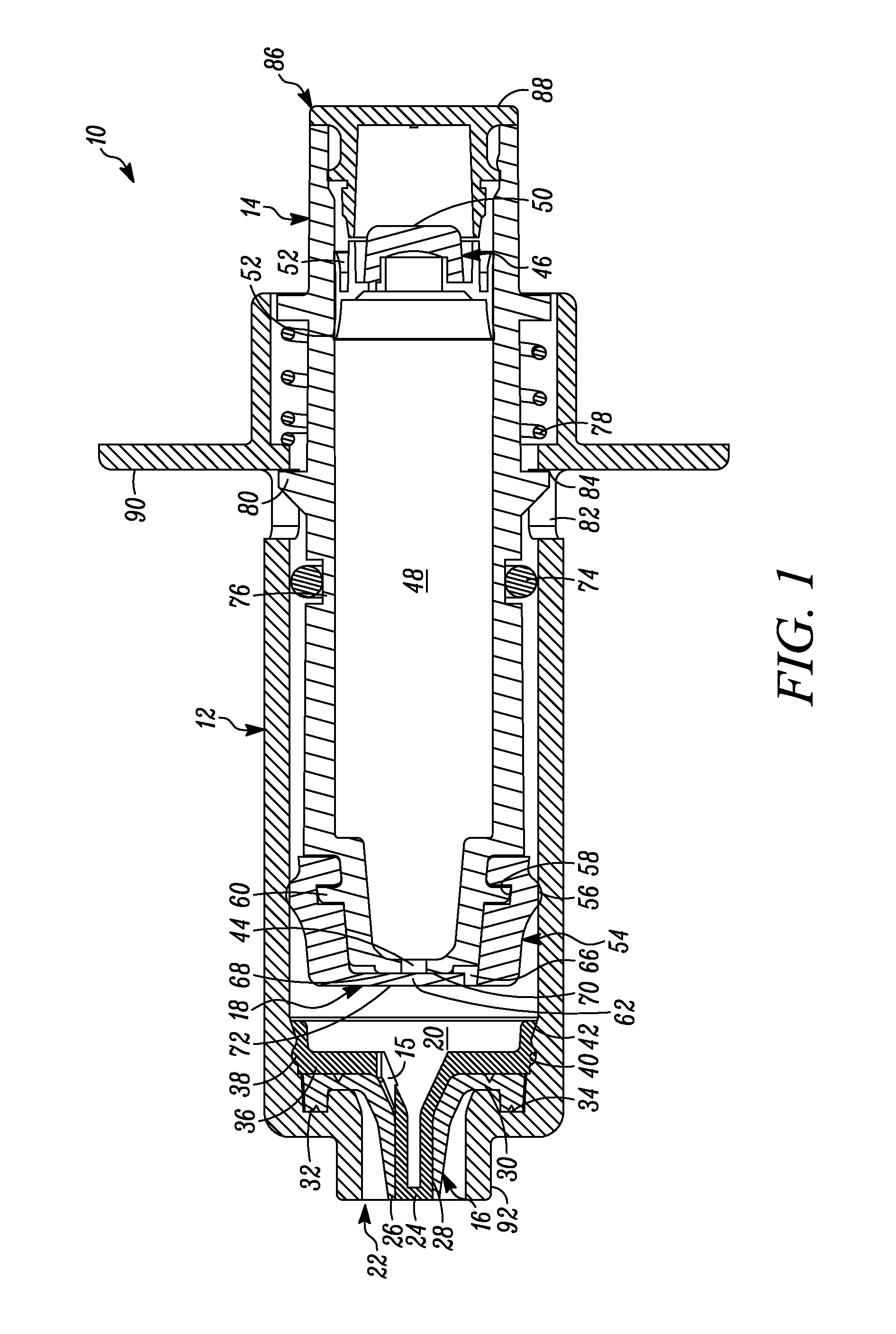
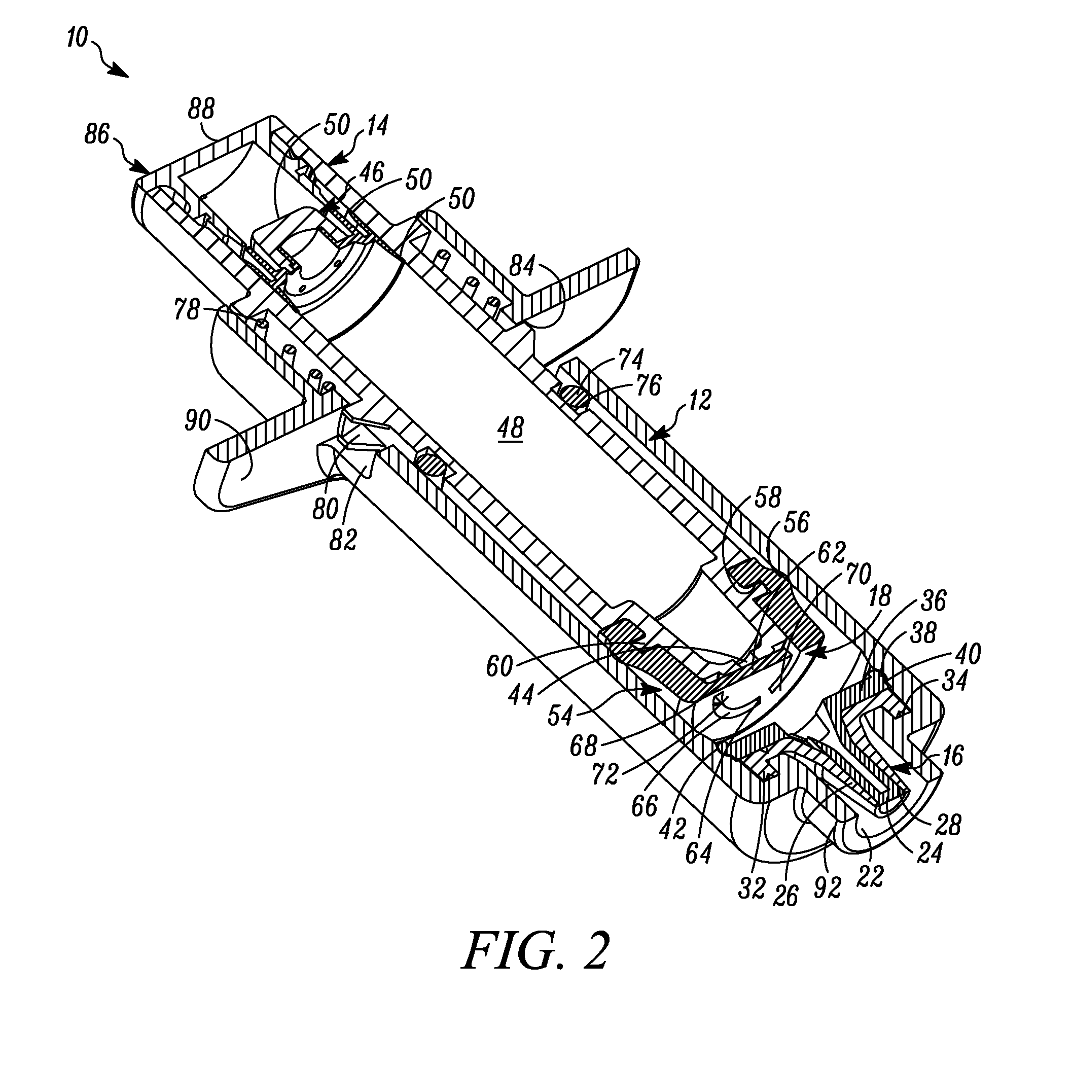
[0061]In FIG. 1 a device is indicated generally by the reference numeral 10. In the illustrated embodiment, the device 10 is a multiple dose syringe; however, as may be recognized by those skilled in the pertinent art based on the teachings herein, the invention may be embodied in and otherwise may be applicable to devices other than multiple dose syringes. The device or syringe 10 includes a body 12, an actuator or plunger 14, a first one-way valve 16 located adjacent to a distal end of the body 12, a second one-way valve 18 located adjacent to a distal end of the plunger 14, and a compression chamber 20 coupled in fluid communication between an inlet 15 of the first valve 16 and an outlet of the second valve 18.

[0062]The first valve 16 is coupled to the body 12 at the distal end thereof. The first valve 16 is in fluid communication with the compression chamber 20 at a proximal side thereof and is in fluid communication with an outlet 22 of the syringe 10 at a distal side thereof. ...


PUM


Abstract

A multiple dose syringe has a first valve defining a first valve opening pressure and a second valve defining a second valve opening pressure. A storage chamber in fluid communication with the second valve stores multiple doses of a substance therein and includes an outlet for dispensing multiple doses of the stored substance therethrough. A compression surface is movable between first and second positions and defines a compression chamber between the compression surface and the first valve. Movement of the compression surface in a direction from the first position toward the second position dispenses substance in the compression chamber through the first valve and out of the syringe. Movement of the compression surface in a direction from the second position toward the first position causes substance to flow from the storage chamber through the second valve and into the compression chamber.

Description

CROSS-REFERENCE TO RELATED APPLICATION[0001]This patent application claims benefit under 35 U.S.C. §119 to similarly-titled U.S. Provisional Patent Application No. 61 / 587,500, filed Jan. 17, 2012, which is hereby incorporated by reference in its entirety as part of the present disclosure.FIELD OF THE INVENTION[0002]The present invention relates to devices for dispensing substances, such as syringes, and more particularly, to such devices that can store multiple doses of the substances to be dispensed.BACKGROUND INFORMATION[0003]A typical syringe includes a body defining a cylindrical or barrel shape, a manually-engageable plunger slidably received within the body, an outlet for dispensing fluid pushed or compressed by the plunger therethrough, and a Luer type fitting at the outlet of the body. A Luer type fitting, such as a LUER-LOK® fitting, is connectable to another Luer fitting on a needle, for example, to form a Luer connection between the needle and body. Typically, the needle ...

Claims


Application Information

Patent Timeline
Patent Type & Authority Applications(United States)
IPC IPC(8): A61M5/315A61J7/00A61M5/178
CPCA61M5/31593A61M5/1782A61M5/204A61M2005/3126A61M2005/3128A61J7/0053G01F11/028G01F11/027B05B9/0426B05B11/028B05B11/1015B05B11/1028B05B11/1064B05B11/1077B05B11/007B05B11/0072B65D83/7535G01F11/02G01F11/025
Inventor PY, DANIEL
Owner DR PY INST LLC
Why Eureka
Try Eureka