Vehicle brake hydraulic pressure control apparatus

Active Publication Date: 2013-07-18
AUTOLIV NISSIN BRAKE SYST JAPAN CO LTD
View PDF4 Cites 13 Cited by
  • Summary
  • Abstract
  • Description
  • Claims
  • Application Information

AI Technical Summary

Benefits of technology

[0011]With the configuration described above, the permissible differential pressure is retrieved based on the map in which the permissible differential pressure is determined in accordance with the velocity of the vehicle body in advance. Thereby, the permissible pressure can be set easily.
[0012]With the configuration described above, the permissible differential pressure is set based on the steering angle and the yaw rate after the first predetermined time period has elapsed since the differential pressure control is started. Therefore, the differential pressure can be controlled as required according to the behaviors of the vehicle, thereby making it possible to enhance the stability.
[0013]With the configuration described above, when the brake fluid pressure of the wheel brake for the front wheel, which was on the high μ side at a time when the differential pressure control was started, is started to be reduced due to the antilock braking control after the differential pressure control is started, the state in which the command pressure is set to the brake fluid pressure, which is exhibited when the brake fluid pressure is started to be reduced, is held for the predetermined time period, while the command pressure is set to the brake fluid pressure of the wheel brake for the front wheel which is on the high μ side. Therefore, the quick and drastic change in brake fluid pressure that would otherwise result from the antilock braking control can be avoided. That is, the change in brake fluid pressure can be suppressed. As a result, it is possible to suppress the vehicle body from being pitched or swayed.
[0014]With the configuration described above, even in the event that the command pressure is set to a lower brake fluid pressure, which is lower than the lock hydraulic pressure at which the antilock braking control is expected to be executed on the high μ, road, due to that the pressure reduction ass

Problems solved by technology

Therefore, a time variation (ΔT1-ΔT2) in timing at which the suppression of the differential pres

Method used


Image

  • Vehicle brake hydraulic pressure control apparatus
  • Vehicle brake hydraulic pressure control apparatus
  • Vehicle brake hydraulic pressure control apparatus

Examples


first embodiment

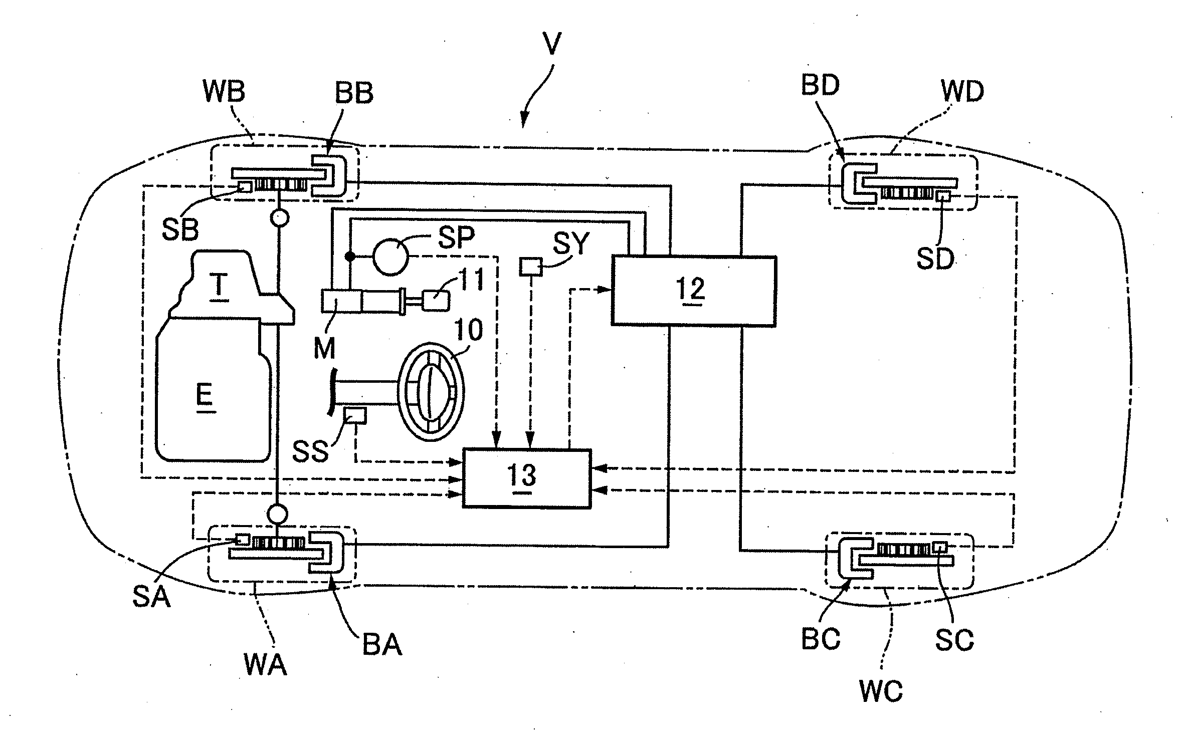
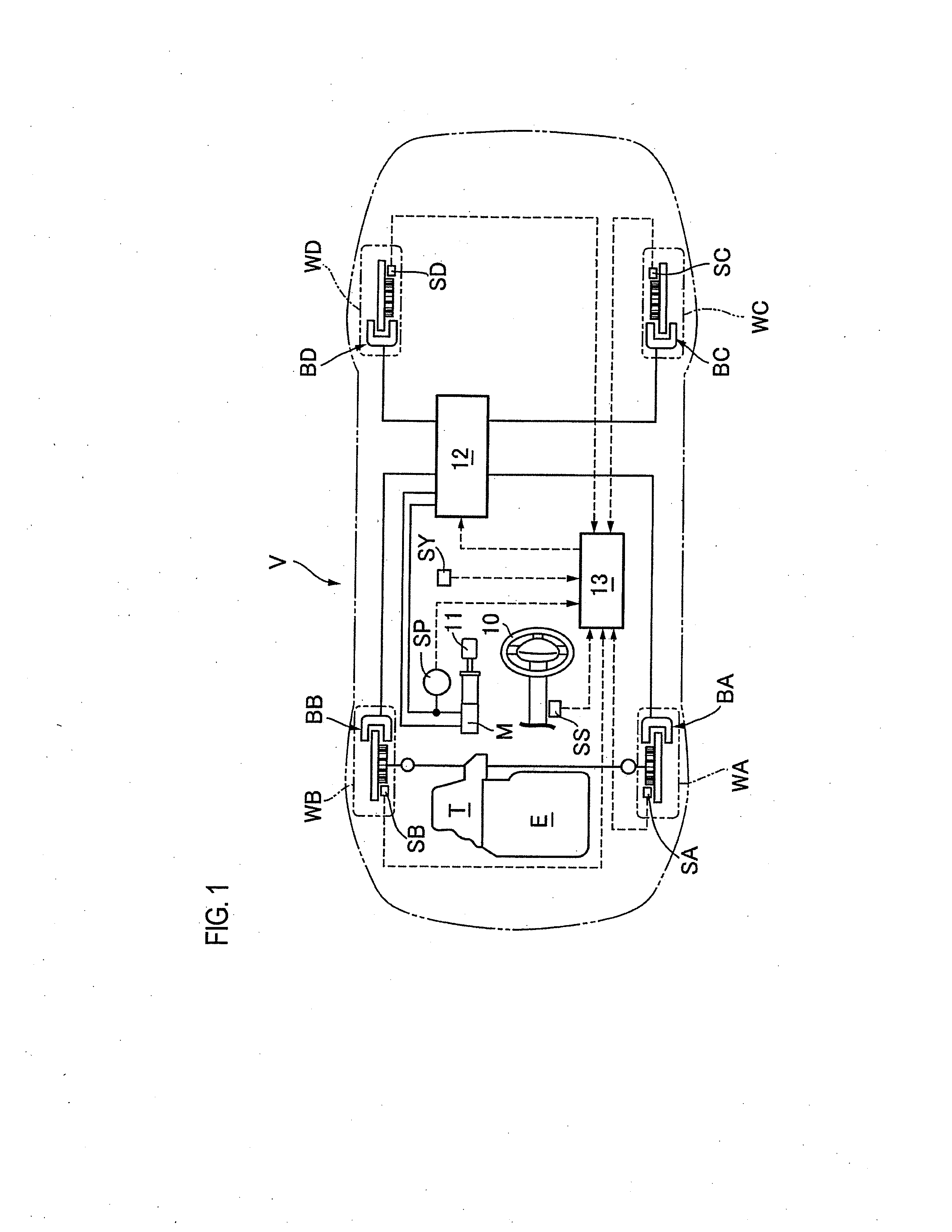
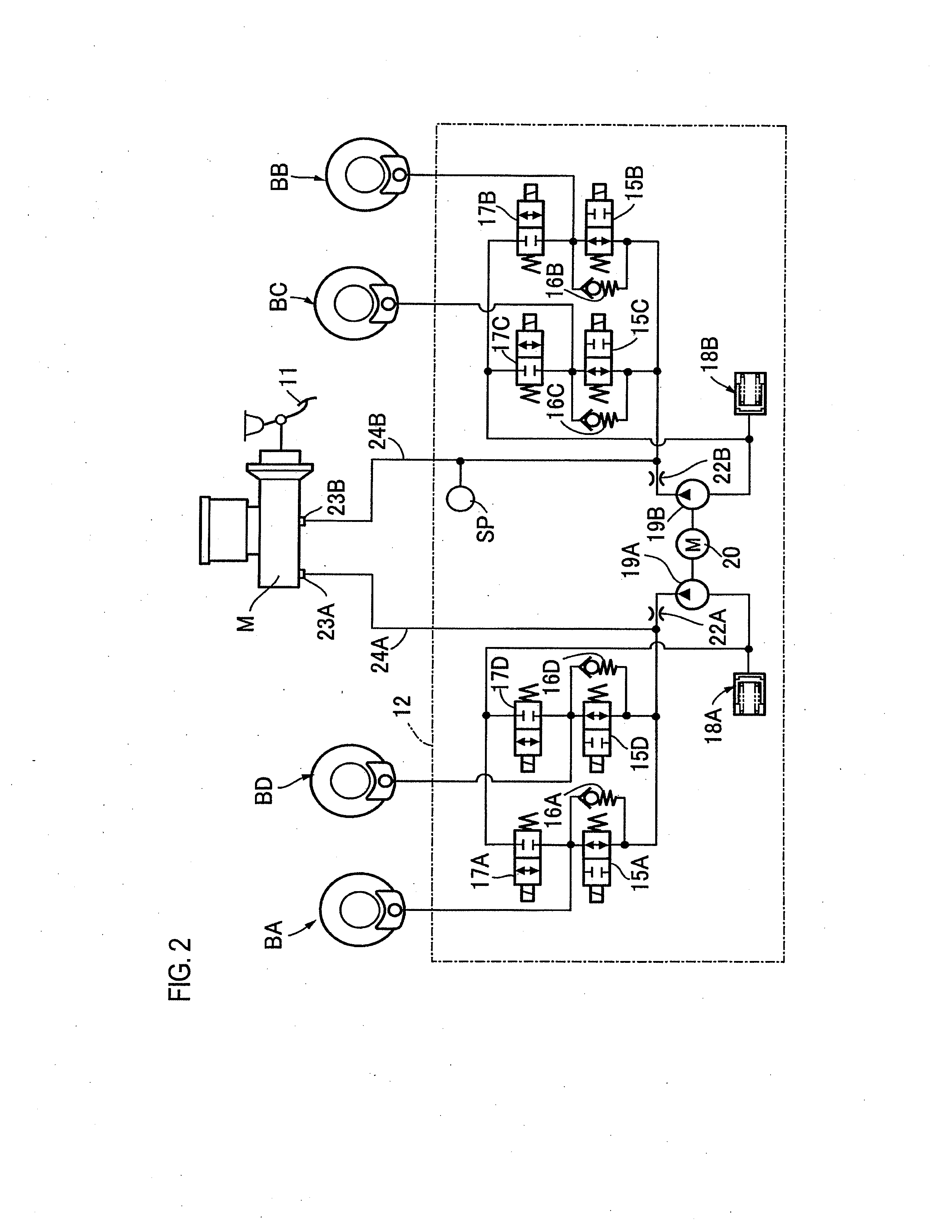
[0043]A first embodiment will be described with reference to FIG. 1 to FIG. 6. In FIG. 1, a vehicle V includes right and left front wheels WA, WB to which a driving force of an engine E is transmitted via a transmission T, and right and left rear wheels WC, WD. A brake pedal 11 (an example of a brake operation member) is operated by a driver and is connected to a master cylinder M. Also, wheel brakes BA, BB, BC, BD, which are operated by the action of brake fluid, are provided in the front wheels WA, WB and the rear wheels WC, WD, respectively. The master cylinder M is connected to the individual wheel brakes BA to BD via a hydraulic pressure adjusting unit 12. The hydraulic pressure adjusting unit 12 can adjust (can increase or decrease) the brake fluid pressures acting on the wheel brakes BA to BD individually in order to prevent the wheels from being locked during braking.

[0044]The operation of the hydraulic pressure adjusting unit 12 is controlled by a hydraulic pressure control...

second embodiment

[0071]Next, a second embodiment will be described with reference to the accompanying drawings. It should be noted that in the following description, similar reference numerals will be assigned to members similar to those of the first embodiment, and the redundant description thereon will be omitted.

[0072]It is assumed that, as shown in FIG. 10, a vehicle V is running in a traveling direction indicated by an arrow 35 with left and right front wheels WA, WB and left and right rear wheels WC, WD being in contact with a low coefficient-of-friction (low μ) road surface and a high coefficient-of-friction (high μ) road surface, respectively (that is, the road surfaces constitute a split road). If a permissible differential pressure is set to be large which is used to execute a differential pressure control in response to the start of the antilock braking control for wheel brakes on the low μ road side, there may be a case where the vehicle brake hydraulic pressure control apparatus accordi...

modified example 1

[0082]The second embodiment has been described premised on the first embodiment. However, the second embodiment is not necessarily premised on the first embodiment. For example, the second embodiment may be modified in the following manner.

[0083]That is, a vehicle brake hydraulic pressure control apparatus according to a modified example 1 includes a hydraulic pressure adjusting unit 12, an antilock braking control section 27, a split road determining section 28, a differential pressure control section 29, and a hydraulic pressure adjusting and driving section 31. The hydraulic pressure adjusting unit 12 can individually adjust brake fluid pressures acting on wheel brakes BA to BD for left and right front wheels WA, WB and left and right rear wheels WC, WD. The antilock braking control section 27 determines as to whether or not executing antilock braking control. Also, the antilock braking control section 27 calculates a hydraulic pressure control amount during the execution of the ...


PUM


Abstract

A vehicle brake hydraulic pressure control apparatus includes a hydraulic pressure adjusting unit, a split road determining section, a differential pressure control section, and a hydraulic pressure adjusting and driving section. The hydraulic pressure adjusting unit individually adjusts brake fluid pressures acting on wheel brakes for wheels. The split road determining section determines whether road surfaces which the wheels are in contact with constitute a split road. In a state where the split road determining section determines during execution of antilock braking control that the road surfaces constitute the split road, the differential pressure control section determines command pressures for the wheel brakes so that differential pressures between the brake fluid pressures of the right and left wheel brakes are equal to or less than a permissible differential pressure. The hydraulic pressure adjusting and driving section controls the hydraulic pressure adjusting unit based on the determined command pressures.

Description

CROSS REFERENCE TO RELATED APPLICATION[0001]This application is based on and claims priority under 35 U.S.C. §119 to Japanese Patent Application Nos. 2011-283937 (filed on Dec. 26, 2011), 2012-13181 (filed on Jan. 25, 2012), and 2012-32402 (filed on Feb. 17, 2012), the entire contents of which are incorporated herein by reference.BACKGROUND[0002]1. Technical Field[0003]The invention relates to a vehicle brake hydraulic pressure control apparatus.[0004]2. Description of the Related Art[0005]JP 2007-55583 A discloses a vehicle brake hydraulic pressure control apparatus that executes antilock braking control for wheel brakes for left and right front wheels and left and right rear wheels of a vehicle independently from each other. In this vehicle brake hydraulic pressure control apparatus, it is controlled so that a difference between brake fluid pressures of the right and left wheel brakes does not become equal to or larger than a predetermined value on a split road in which coefficien...

Claims


Application Information

Patent Timeline
IPC IPC(8): B60T8/1764
CPCB60T8/1755B60T7/12B60T8/1764
Inventor KOBAYASHI, MASASHIHIROSE, TOMONORI
Owner AUTOLIV NISSIN BRAKE SYST JAPAN CO LTD
Why Eureka
Try Eureka