Hybrid Adaptively Sampled Distance Fields

a distance field and hybrid technology, applied in the direction of machine control, process control, instruments, etc., can solve the problems of time-consuming and expensive manual testing, inability to accurately reproduce the desired shape, and undesirable gouges or nicks on the surface of the final shape of the workpiece, etc., to improve usability and processing the model, improve the usability and time efficiency, and improve the effect of usability

Active Publication Date: 2013-07-18
MITSUBISHI ELECTRIC RES LAB INC
View PDF1 Cites 15 Cited by
  • Summary
  • Abstract
  • Description
  • Claims
  • Application Information

AI Technical Summary

Benefits of technology

[0043]It is an object of present invention to provide a space and time efficient method for representing and rendering such high precision models for machining simulation. It is another object of various embodiments of the invention to provide an alternative representation of a model of an object to improve usability and processing the model. It is further object of some embodiment to provide the model that improves speed and accuracy of reconstruction of composite boundary of the object, and facilitates processing of the model for various simulation and graphic rendering tasks.
[0051]Additionally the distance field samples are used to improve the quality and performance of the regeneration and rendering of the hybrid ADF. Furthermore, the hybrid ADF simplifies the culling procedure, increases effectiveness of the rendering process, provides more accurate approximation of the surface of the object, and opens an opportunity for flexible representation of the object.

Problems solved by technology

The G-Codes generated by the CAM system may not produce an exact replication of the desired shape.
In addition, the movement of the NC tool is governed by motors of the NC machining machine, which have predetermined speeds, accelerations, ranges of motion, so that the actual tool motions may not exactly follow the NC machine instructions.
In some situations, these discrepancies can result in undesirable gouges or nicks in the surface of the final shape of the workpiece with sizes on the order of a few micrometers in depth and width, and tens of micrometers in length.
This manual testing is time consuming and expensive.
They conclude that research in this field is limited by the difficulty of implementing complex mathematical formulations of sweeps in computer software and that computing the boundaries of swept volumes remains a challenging problem requiring better visualization tools and more accurate methods.
However, those methods do not generalize to complex shapes and complex tool paths.
However, visualizing the full model at high precision is prohibitively slow.
The accuracy of each of these polygonal methods is limited by the polygonal representation of the object model.
Thus, those methods either have limited accuracy or they have prohibitive processing times and memory requirements for generating high precision models of swept volumes or both.
In addition, methods that approximate the swept volume as a series of discrete time steps have limited precision between the time steps, and are subject to aliasing artifacts.
Dexel methods typically suffer from limited resolution, especially in directions not aligned with the z-axis, and are not suitable for generating high precision models of swept volumes.
Those methods both have accuracy limited by the size of the smallest voxel used to represent the swept volumes.
However, implicit surfaces can be difficult to render, and a suitable implicit representation for an arbitrarily complex tool shape is difficult to define.
For more complex objects an analytic function may not be possible.
For still more complex objects, there may not be a simple numerical procedure that can be used to compute the distance field of the object.
For example, a machined workpiece can have a very complex surface such that a numerical procedure cannot compute the distance field of the object.
Regular sampling of a distance field is very simple, but may not be very efficient.
Likewise, there may be regions of space where the distance field is changing quickly such that the number of samples is not sufficient to accurately reconstruct the distance field (under-sampled).
However, to obtain very high accuracy (˜1 micron) using a sampled ADF can require a prohibitively large amount of memory and processing time when simulating a large workpiece.
The procedure for determining the subset must be fast but also accurate or the resulting composite boundary will not be correct.
However, the ray sampling procedure can result in errors in the determination of the subset of distance field that cannot be easily detected.
However, the reconstruction of this very accurate surface can be slow limiting the usability of the method.

Method used


Image

  • Hybrid Adaptively Sampled Distance Fields
  • Hybrid Adaptively Sampled Distance Fields
  • Hybrid Adaptively Sampled Distance Fields

Examples


Embodiment Construction

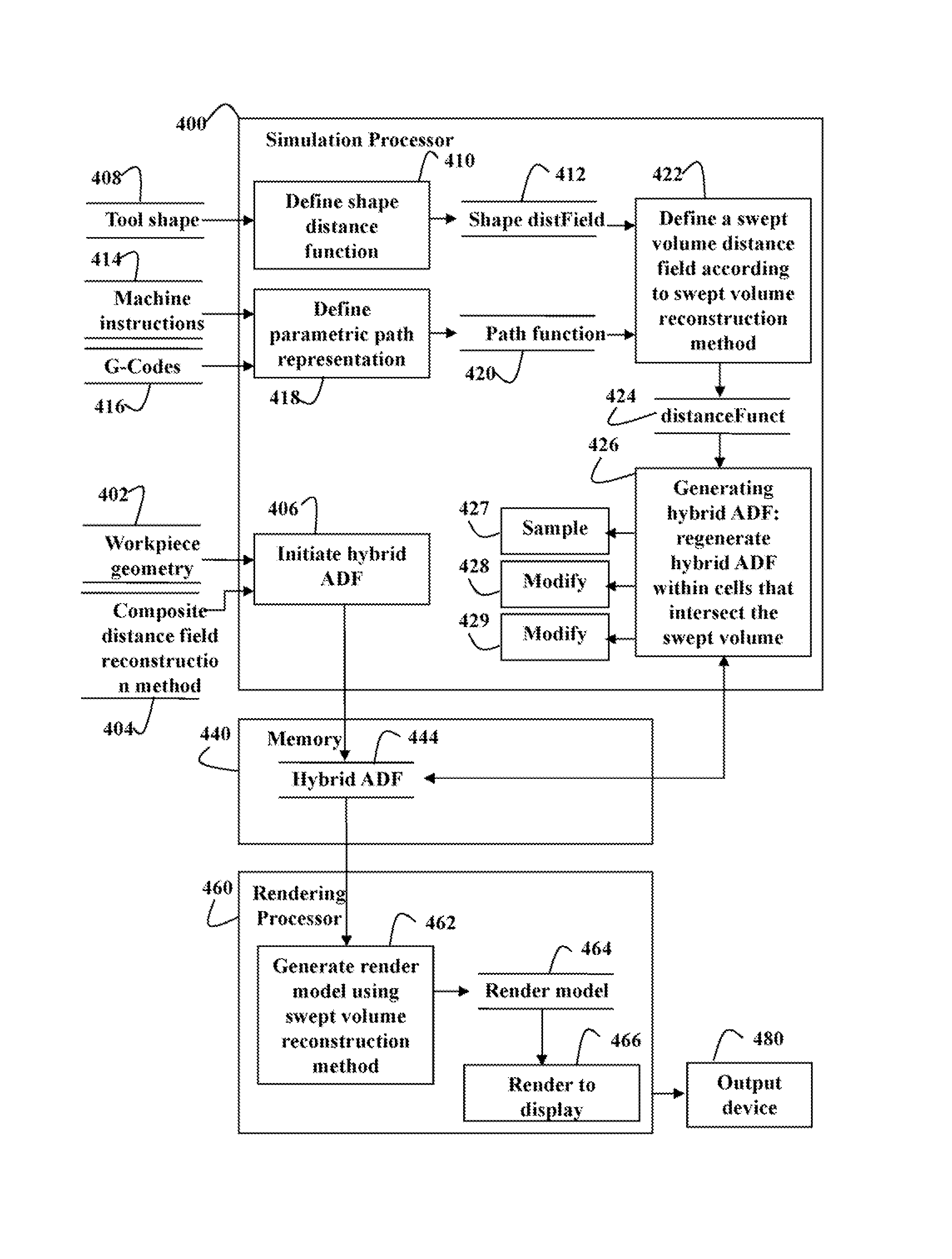
[0076]System and Method Overview

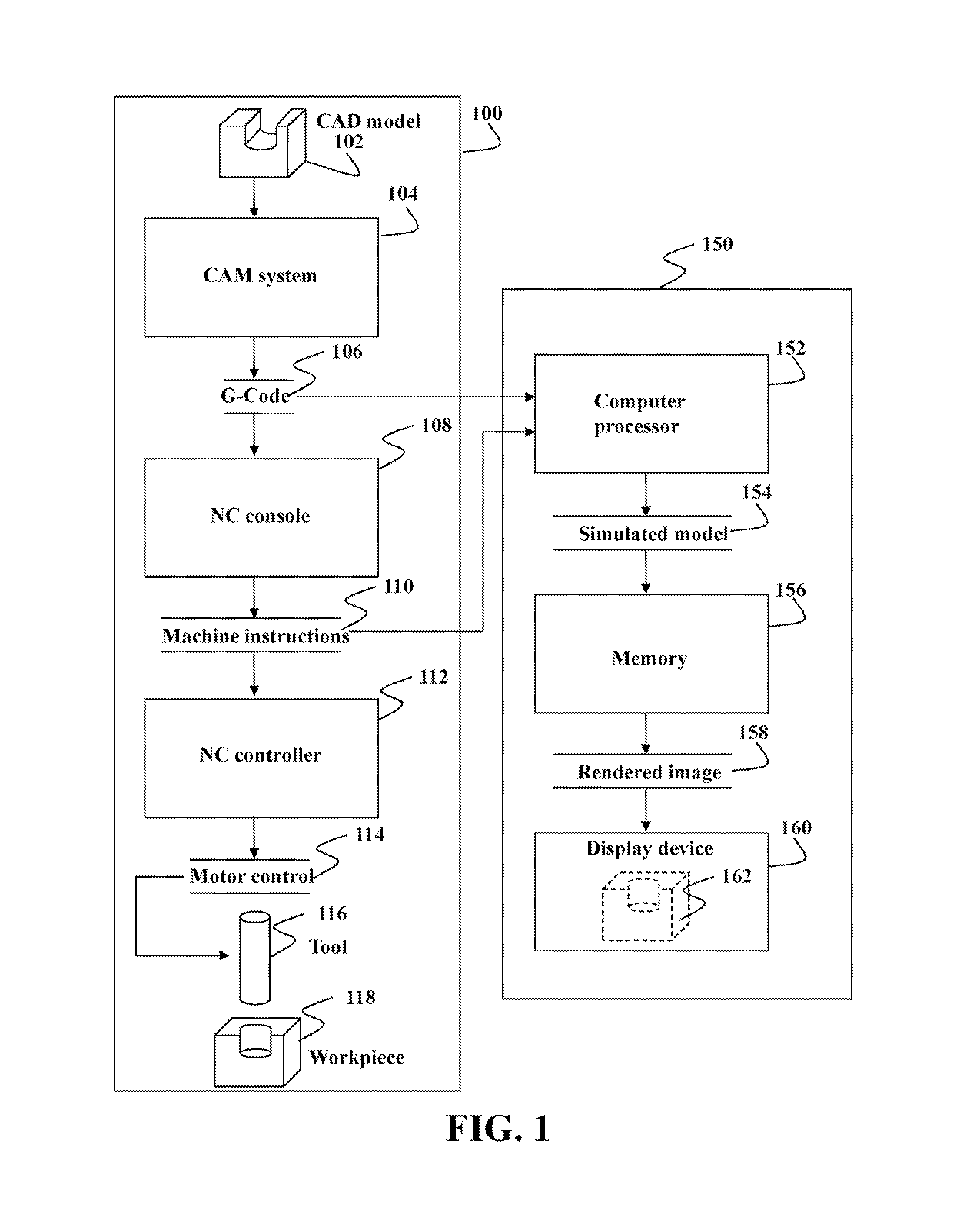
[0077]FIG. 1 shows an example of an NC machining system 100, and a numerically controlled (NC) machining simulation system 150. In the NC machining system 100, a computer aided design (CAD) model 102 is input to a computer aided manufacturing (CAM) system 104, which generates G-Codes 106 for controlling the NC machining system. During NC machining, the G-Codes are input to an NC machining console 108, which processes the G-Codes to produce a corresponding set of NC machine instructions 110. The NC machine instructions are input to an NC controller 112, which produces a set of motor control signals 114 to move a tool 116 relative to a workpiece 118 to machine, e.g., to mill the workpiece.

[0078]The simulation system 150 can take as input either the G-Codes 106 generated by the CAM system 104, or the NC machine instructions 110 generated by the NC console 108. The input to the simulation system is read by a computer processor 152, which simulates machini...


PUM


Abstract

A computer program product for processing a model of an object according to a set of instructions includes a non-transitory computer-readable memory storing a model of an object represented by a hybrid adaptively sampled distance field (ADF), wherein the model includes a hierarchy of cells, wherein at least one cell includes a set of distance functions forming at least part of a boundary of the object and a set of distance samples of at least some of the distance functions, such that a processor executing the set of instructions processes the model of the object.

Description

FIELD OF THE INVENTION[0001]The invention relates generally to simulating numerically controlled (NC) machining, and more particularly to simulating NC machining using hybrid adaptively sampled distance fields.BACKGROUND OF THE INVENTION[0002]Numerically Controlled Machining[0003]Simulating the process of numerically controlled (NC) machining is of fundamental importance in computer aided design (CAD) and computer aided manufacturing (CAM). During simulation, a computer model of a workpiece is edited with a computer representation of an NC machining tool and a set of NC machining tool motions to simulate the machining process.[0004]The workpiece model and tool representation can be visualized during the simulation to detect potential collisions between parts, such as the workpiece and the tool holder, and after the simulation to verify the final shape of the workpiece.[0005]The final shape of the workpiece is affected by the selection of the tool and the tool motions. Instructions f...

Claims


Application Information

Patent Timeline
Patent Type & Authority Applications(United States)
IPC IPC(8): G06F17/10
CPCG05B19/4069G06T2200/04G06T17/005
Inventor SULLIVAN, ALAN
Owner MITSUBISHI ELECTRIC RES LAB INC
Why Eureka
Try Eureka