Linear electric motor for artificial lift system

a technology of electric motors and electric motors, applied in the direction of dynamo-electric machines, electrical apparatus, fluid removal, etc., can solve the problems of high cost of pumps and sucker rods connecting the downhole pump to the pumping jack, and suffer from several technical problems

Active Publication Date: 2013-07-25
OILFIELD EQUIP DEVMENT CENT
View PDF2 Cites 28 Cited by
  • Summary
  • Abstract
  • Description
  • Claims
  • Application Information

AI Technical Summary

Benefits of technology

[0007]Embodiments of the present invention generally relate to a linear electric motor for an artificial lift system. In one embodiment, a submersible linear electric motor for use in a wellbore includes a stator and a head. The stator includes a tubular housing; support rings disposed in and along the housing and having an inner diameter; and annular coils disposed in and along the housing between the support rings. Each coil has: a magnetically permeable stator core having a cavity formed therein and an inner diameter greater than the support ring diameter; and a winding disposed in the cavity. The head is disposed in the housing and longitudinally movable relative thereto. The head has: a shaft; magnetically permeable annular head cores disposed along the shaft and having an outer diameter; annular permanent magnets disposed along the shaft between the head cores; and a protector disposed around an outer surface of each magnet and having an outer diameter less than the core diameter. The support ring diameter and the head core diameter correspond to form a clearance fit or line fit between the head cores and the support rings.

Problems solved by technology

However, this system of artificial lift is very inefficient.
Not only are the pumps and the sucker rod connecting the downhole pump to the pumping jack very expensive, but they also suffer from several technical problems.
One of the major problems is that, since most wells are not straight, the sucker rod usually rubs against the tubing in a number of places.
This problem is even more severe in wells that are intentionally directionally drilled and whose deviation from perfect straightness can be quite large.
Not only does this wear the sucker rod and the tubing, necessitating the costly replacement of both, but the friction between the sucker rod and the tubing wastes energy and requires that more powerful motors be used to operate the pumping jack.
In cases where the sucker rod completely wears through the tubing, there is also the problem of losing production from the production tubing back into the well casing.
Other problems associated with present sucker rod pumping systems are breakage of the bridle line connecting the pumping jack head to the polish rod, freezing of engine fluids in cold weather, pollution from engine exhaust, and leaks around the wellhead associated with the moving seal between the polish rod and the stuffing box.

Method used


Image

  • Linear electric motor for artificial lift system
  • Linear electric motor for artificial lift system
  • Linear electric motor for artificial lift system

Examples


Embodiment Construction

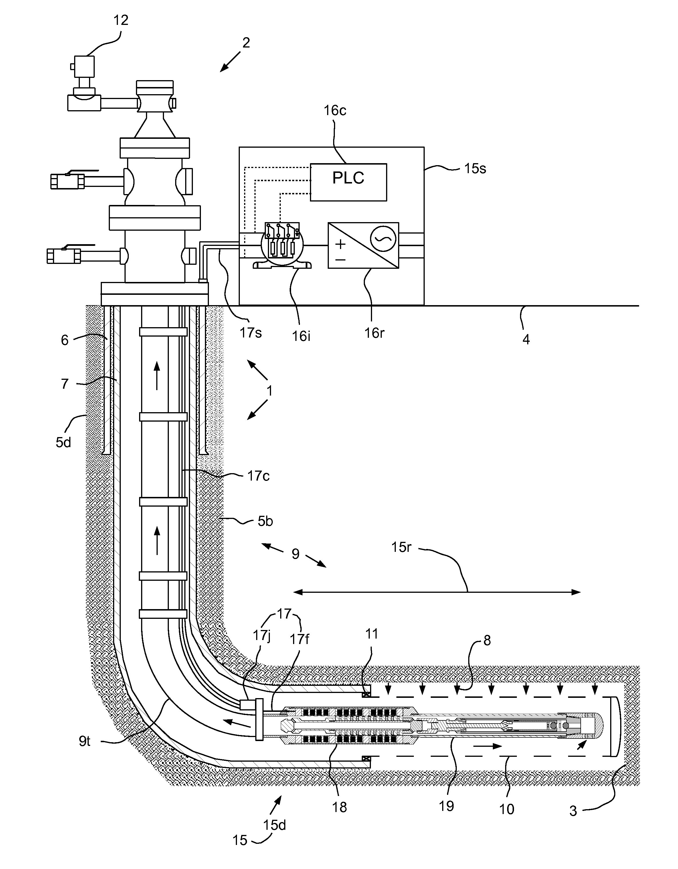
[0017]FIG. 1 illustrates an artificial lift system (ALS) 15 pumping production fluid 8 from a wellbore 3, according to one embodiment of the present invention. The production fluid 8 may be crude oil, bitumen, heavy crude oil, or oil shale.

[0018]The ALS 15 may include a motor driver 15s, a power cable 17, and a downhole assembly 15d. The downhole assembly 15d may include a submersible linear electric motor (LEM) 18 and a reciprocating pump 19. The wellbore 3 may be part of a completed well 1. The well 1 may further include a wellhead 2 located adjacent to a surface 4 of the earth. The wellbore 3 may extend from the surface 4 vertically through a non-productive formation 5d and horizontally through a hydrocarbon-bearing formation 5b (aka reservoir). Alternatively, the horizontal portion of the wellbore 3 may be other deviations besides horizontal. The well 1 may further include a surface casing 6 extending from the wellhead 2 into the wellbore 3 and sealed therein with cement. The we...


PUM

PropertyMeasurementUnit
inner diameteraaaaaaaaaa
diameteraaaaaaaaaa
outer diameteraaaaaaaaaa

Abstract

A method for pumping production fluid from a wellbore includes deploying a downhole assembly of an artificial lift system (ALS) into the wellbore. The downhole assembly includes a linear electric motor (LEM) and a pump. The method further includes operating the LEM, thereby reciprocating the pump and lifting production fluid from the wellbore to surface. The LEM includes a stator and a reciprocating head having permanent magnets. The production fluid leaks through an interface formed between the head and the stator.

Description

BACKGROUND OF THE INVENTION[0001]1. Field of the Invention[0002]Embodiments of the present invention generally relate to a linear electric motor for an artificial lift system.[0003]2. Description of the Related Art[0004]Crude oil is often produced using a sucker rod pump driven by a surface mounted pumping jack. However, this system of artificial lift is very inefficient. Not only are the pumps and the sucker rod connecting the downhole pump to the pumping jack very expensive, but they also suffer from several technical problems.[0005]One of the major problems is that, since most wells are not straight, the sucker rod usually rubs against the tubing in a number of places. This problem is even more severe in wells that are intentionally directionally drilled and whose deviation from perfect straightness can be quite large. Not only does this wear the sucker rod and the tubing, necessitating the costly replacement of both, but the friction between the sucker rod and the tubing wastes ...

Claims


Application Information

Patent Timeline
Patent Type & Authority Applications(United States)
IPC IPC(8): E21B43/12
CPCH02K33/16Y10T29/49009E21B43/128H02K41/031
Inventor FILIPPOV, ALEXANDR VASILIEVICHSHARIPOV, SALIHYAN SHAKIRIANOVICHSAGALOVSKIY, VLADIMIR IOSIFOVICHSAGALOVSKIY, ANDREI VLADIMIROVICH
Owner OILFIELD EQUIP DEVMENT CENT
Why Eureka
Try Eureka