Laser processing machine

a laser processing machine and laser technology, applied in metal-working equipment, welding equipment, manufacturing tools, etc., can solve the problems of time-consuming examination, error in plane coordinate system, and also required correction operation, so as to achieve the effect of calibrating an error in the irradiation position of a laser beam with eas

Active Publication Date: 2013-07-25
KATAOKA
View PDF3 Cites 39 Cited by
  • Summary
  • Abstract
  • Description
  • Claims
  • Application Information

AI Technical Summary

Benefits of technology

[0014]According to the present invention, it is possible to realize a laser processing machine capable of calibrating an error in an irradiation position of a laser beam with ease.

Problems solved by technology

In a scan with the optical axis of the laser beam being displaced, errors in a plane coordinate system are caused due to reasons including a rotational positioning error of a mirror of the galvano scanner, optical distortion of the condensing lens, and the like.
However, it is very time consuming to examine the pattern formed on the test piece using the microscope, and it is also necessary to provide the microscope with high precision at a workplace since such correction operation is always performed in adjusting the processing machine at the time of assembly and delivery.
Moreover, the correction operation is also required at the time of optically adjusting a laser oscillator, exchanging or changing a focal point of the condensing lens, which are troublesome.

Method used


Image

  • Laser processing machine
  • Laser processing machine
  • Laser processing machine

Examples


Embodiment Construction

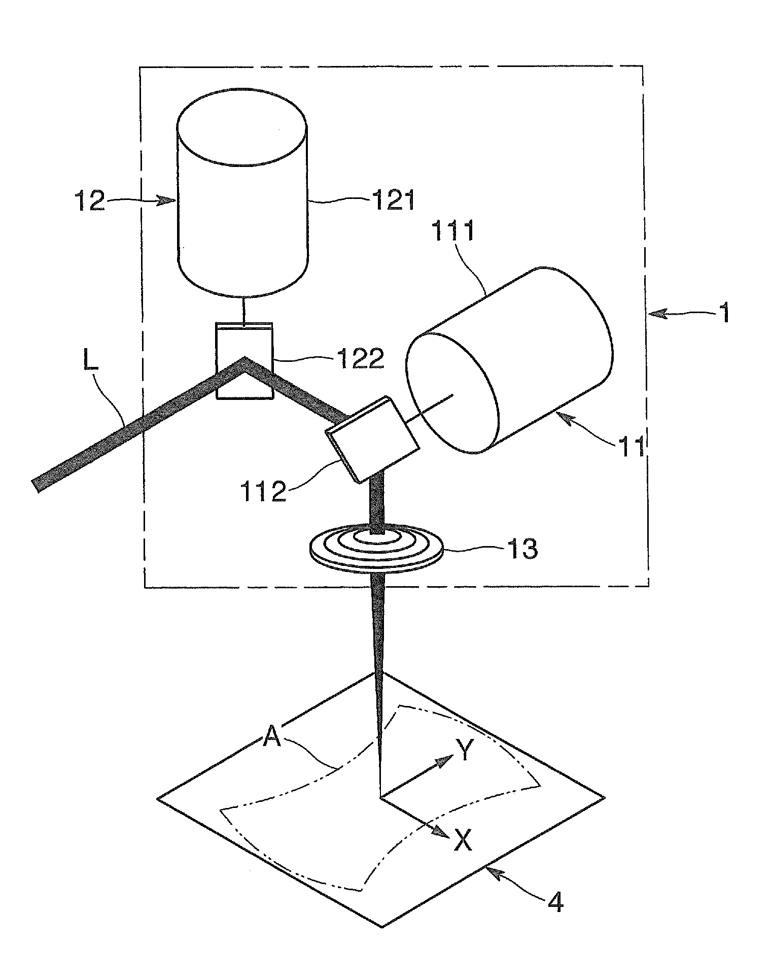
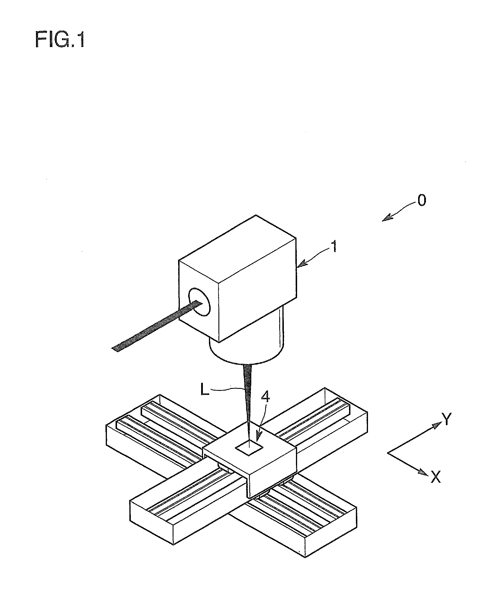
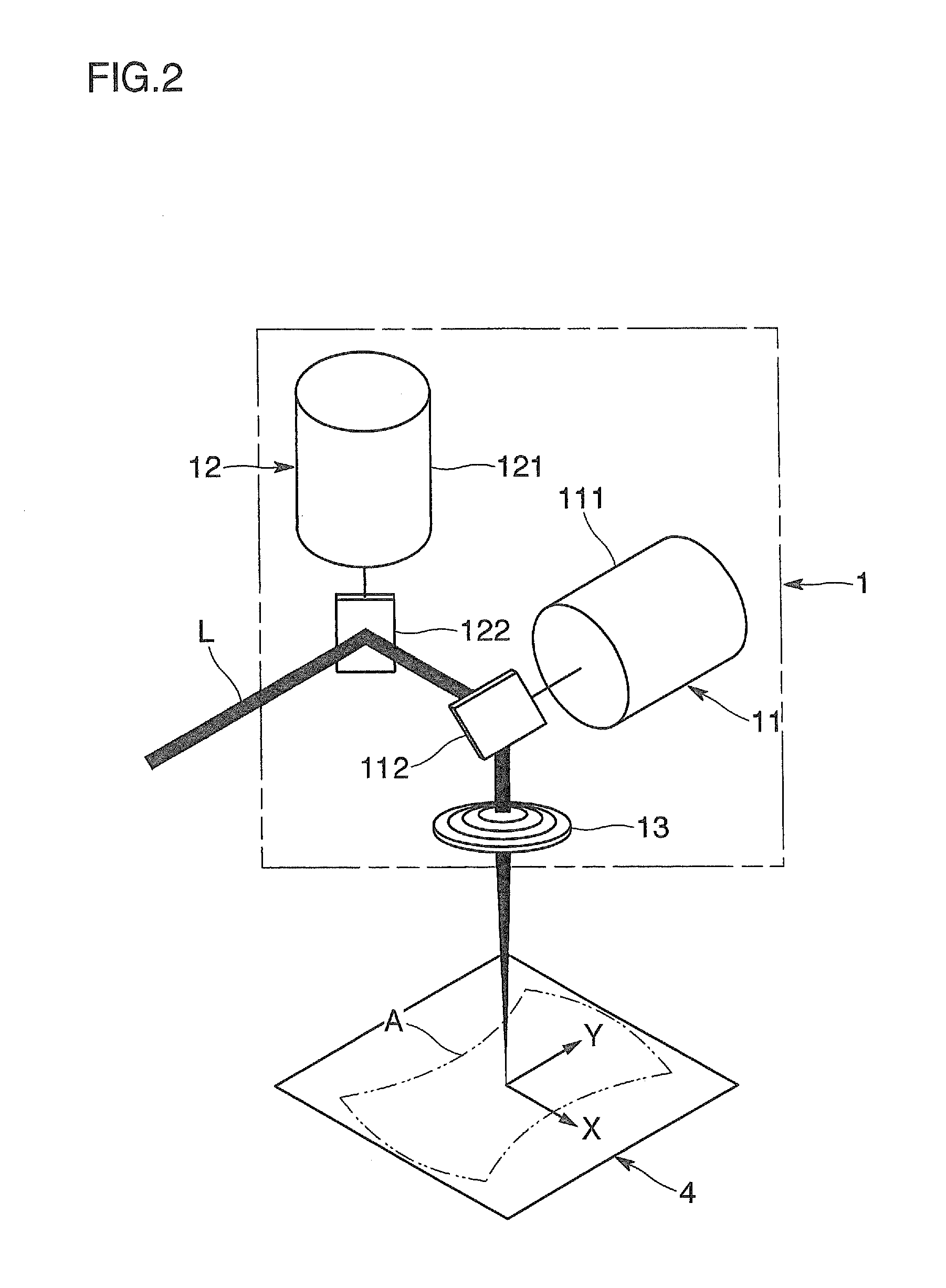
[0023]An embodiment of the present invention will be explained with reference to the drawings. As shown in FIG. 1 and FIG. 2, a laser processing machine 0 of this embodiment includes a mount 4 that supports a workpiece to be processed, and a laser irradiation device 1 that irradiates the workpiece with a laser beam L, and applies laser processing to a freely-selected position of the workpiece.

[0024]The mount 4 supports the workpiece at the time of the laser processing. A top surface of the mount 4 that serves as a predetermined surface on which the workpiece is arranged has a grid pattern indicating position coordinates of respective positions on the surface. Although the form of the grid pattern is not particularly limited, FIG. 6 shows an example in which innumerable points (circles each having a diameter of 0.5 mm, for example) 41 are provided at predetermined intervals (1 mm intervals, for example) in an X-axis direction and a Y-axis direction that is perpendicular to the X-axis...


PUM

PropertyMeasurementUnit
diameteraaaaaaaaaa
diameteraaaaaaaaaa
opticalaaaaaaaaaa

Abstract

A processing machine includes mirrors and to reflect a beam L oscillated from a laser oscillator to a predetermined surface on which a workpiece is arranged, optical axis operating mechanisms and to position an optical axis of the beam L at a desired target irradiation position by changing directions of the mirrors and, a camera sensor to capture an image of the target irradiation position and its periphery reflected in the mirror, and an error calibration mechanism to detect an error between the target irradiation position instructed to the optical axis operating mechanisms and an actual position of the optical axis of the beam L in the predetermined surface by referring to the image captured by the camera sensor. A correction amount to the optical axis operating mechanisms and is determined based on the error to irradiate the target irradiation position with the beam L during processing.

Description

TECHNICAL FIELD[0001]The present invention relates to a laser processing machine that applies processing by irradiating a freely-selected position of a workpiece with a laser beam.BACKGROUND ART[0002]Some types of processing machines that irradiate a freely-selected position of a workpiece with a laser beam displace an optical axis of the laser beam. As a concrete measure to change a direction of the optical axis, a combination of a galvano scanner and a condensing lens is often employed (refer to, for example, the following patent documents).[0003]In a scan with the optical axis of the laser beam being displaced, errors in a plane coordinate system are caused due to reasons including a rotational positioning error of a mirror of the galvano scanner, optical distortion of the condensing lens, and the like. It is necessary to remove such errors in advance before performing laser processing.[0004]Previously, a test piece is subjected to the laser processing for a test pattern, and the...

Claims


Application Information

Patent Timeline
Patent Type & Authority Applications(United States)
IPC IPC(8): B23K26/04B23K26/067B23K26/00
CPCB23K26/041B23K26/067B23K26/04B23K26/0807B23K26/032B23K26/0643B23K26/0665B23K26/0853B23K26/042B23K26/082
Inventor SUZUKI, MASAMINISHI, NORIOMATSUMOTO, JUNICHIYONEYAMA, NOBUTAKATOKUOKA, SATOSHIKATO, ETSUSHI
Owner KATAOKA
Why Eureka
Try Eureka