

Turbomachine casing assembly
a technology for turbines and casings, applied in the direction of machines/engines, stators, liquid fuel engines, etc., can solve the problem of more difficult to devise casing arrangements
- Summary
- Abstract
- Description
- Claims
- Application Information
AI Technical Summary
Benefits of technology
Problems solved by technology
Method used
Image

Examples
Embodiment Construction
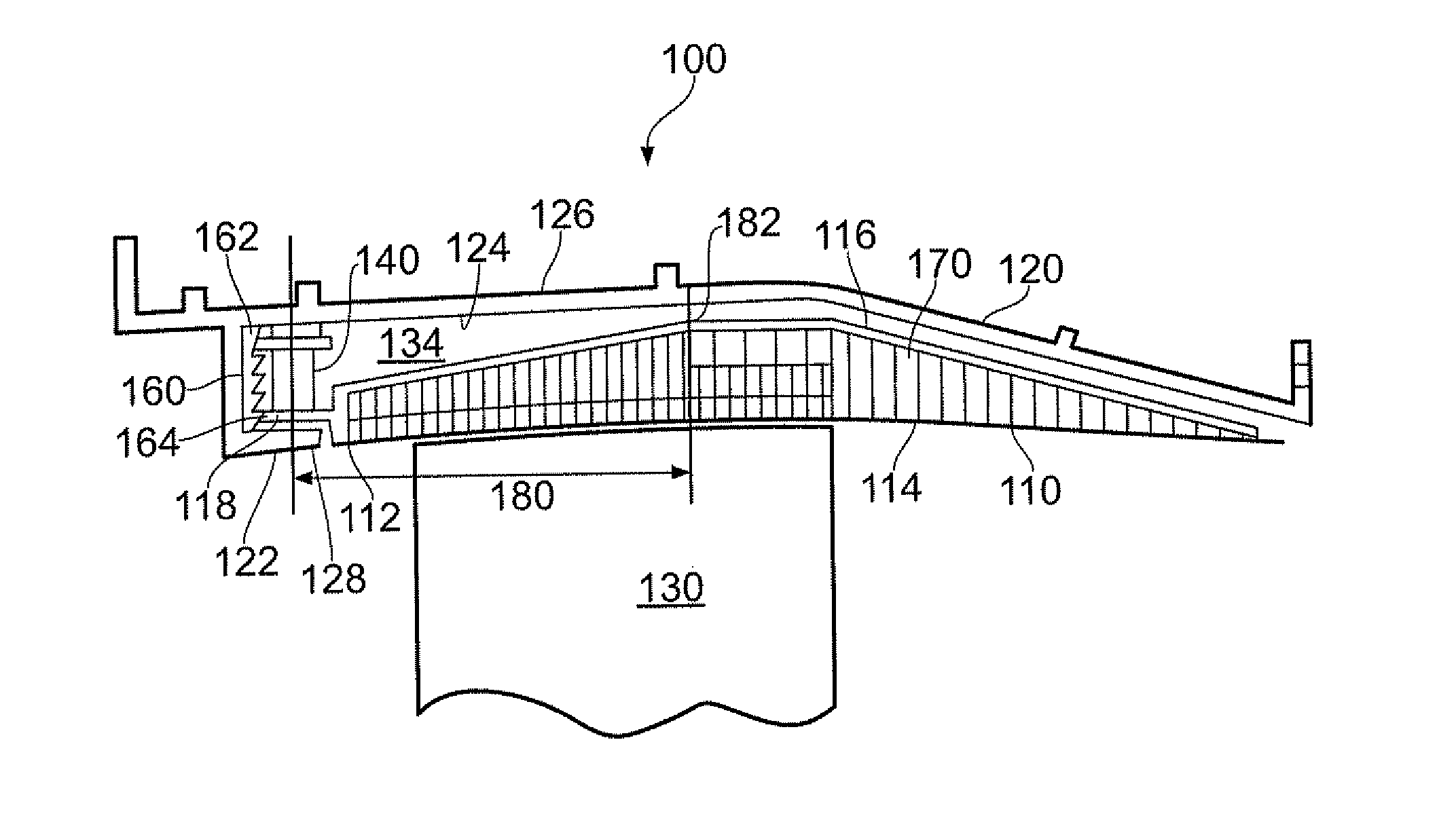
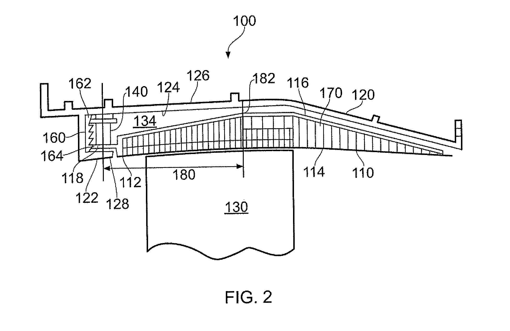
[0062]Referring to FIG. 2, a fan casing assembly according to a first embodiment of the invention is designated generally by the reference numeral 100 and comprises a first casing element 110 and a second casing element 120.
[0063]The first casing element 110 has a first end 112, a radially proximal surface 114 and a radially distal surface 116, and the second casing element 120 has a first end 122, a radially proximal surface 124 and a radially distal surface 126.
[0064]The first casing element 110 at least partially encloses one or more rotating aerofoil structures 130. These aerofoil structures 130 may comprise blades of a turbomachine, in particular compressor fan blades. The second casing element 120 is disposed radially distal to the first casing element 110.
[0065]The turbomachine casing assembly 100 comprises a plurality of first casing elements 110 circumferentially disposed about a curve defined by the blade tip path of the one or more aerofoil structures 130 of the turbomach...
PUM
 Abstract
Description
Claims
Application Information