Artificial knee joint

a knee joint and artificial technology, applied in knee joints, prostheses, medical science, etc., can solve the problems of inability to expect the knee to rotate largely, the post is drastically worn locally, and the knee joint may become unstable so as to improve the stability in the rotation direction, the flexibility of the elliptical spherical sliding portion is enhanced, and the width of the elliptical spherical sliding portion is increased

Inactive Publication Date: 2013-07-25
KYOCERA MEDICAL CORP
View PDF1 Cites 16 Cited by
  • Summary
  • Abstract
  • Description
  • Claims
  • Application Information

AI Technical Summary

Benefits of technology

[0022]In the artificial knee joint according to the present invention, the width of the elliptical spherical sliding portion is widened from the opening toward the posterior end. When the angle of flexion of the knee joint becomes large, the width of the elliptical spherical sliding portion is increased with respect to the width of the spine. That is, when the angle of flexion of the knee joint becomes large, the flexibility of the elliptical sph...

Problems solved by technology

Thus, when the crucial ligament is cut, the knee joint also possibly becomes unstable in the direction of rotation in the extension and slight flexion positions.
In the technique disclosed in Patent Document 1, however, the load from the femoral component concentrates on the post in flexion, so that the post drastically wears locally to be deformed or broken.
Also, in the deep flexion, the post interferes with the opening between the femoral condyles at a small rotation angle, which...

Method used


Image

  • Artificial knee joint
  • Artificial knee joint
  • Artificial knee joint

Examples


first embodiment

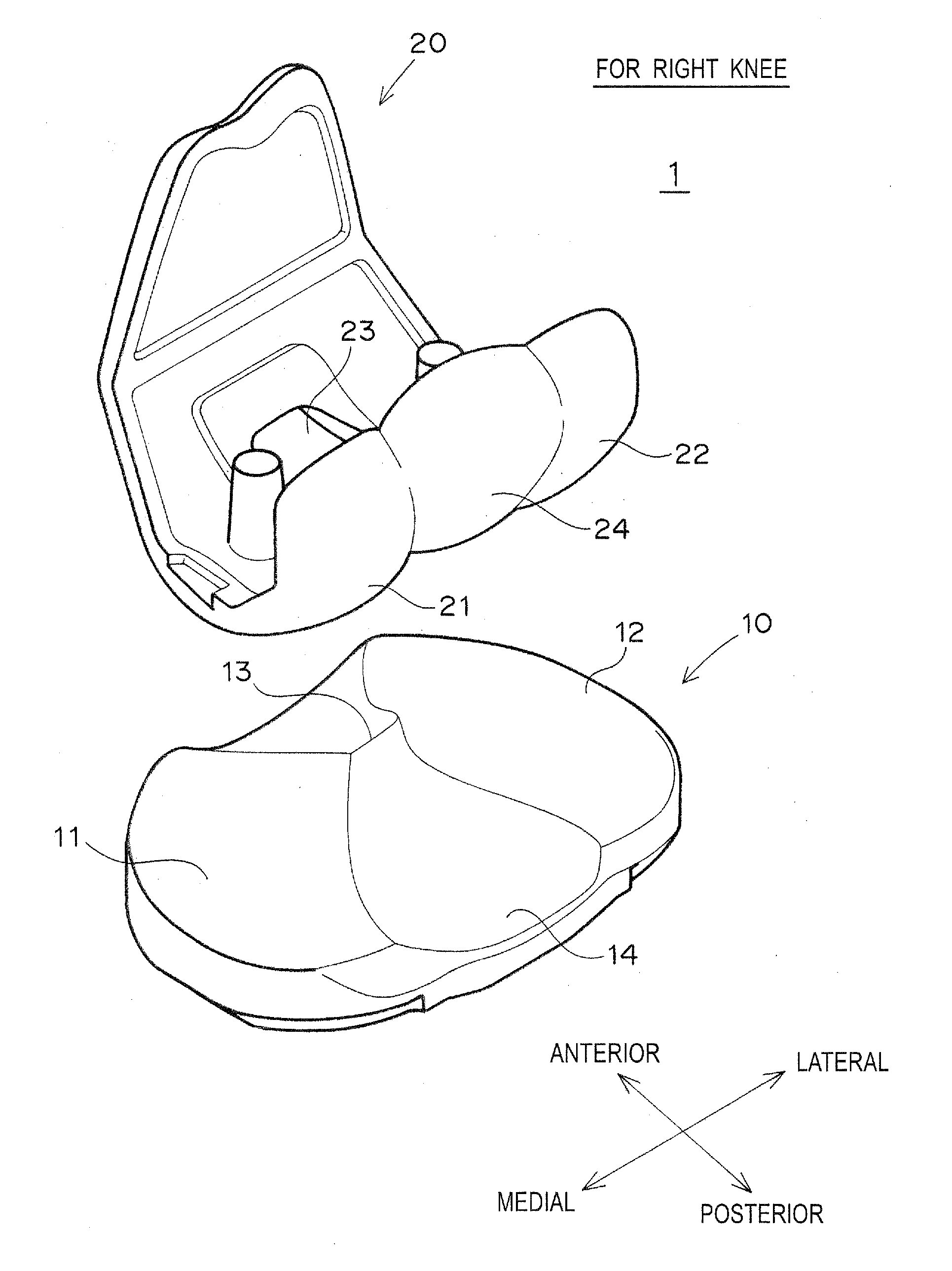
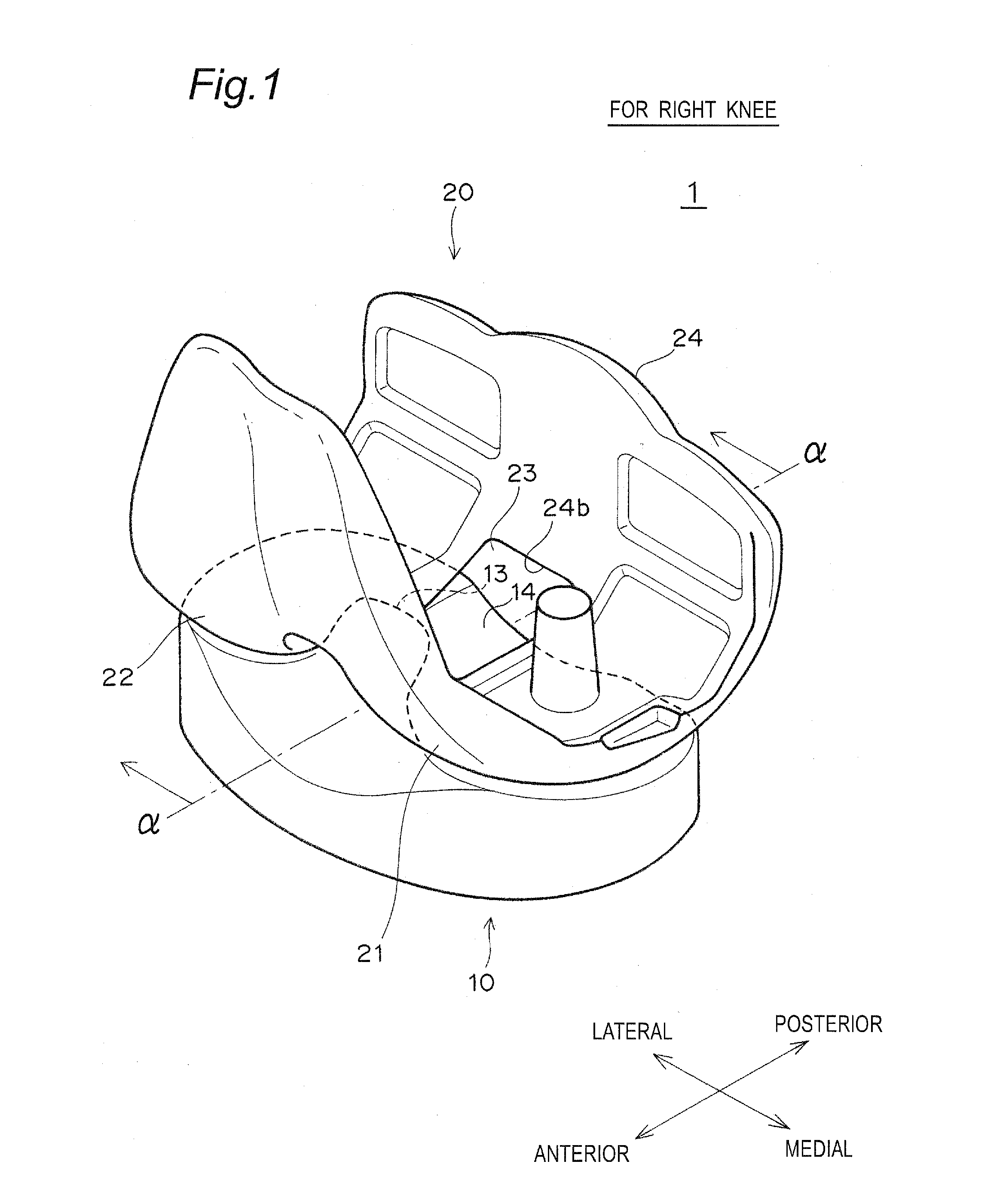
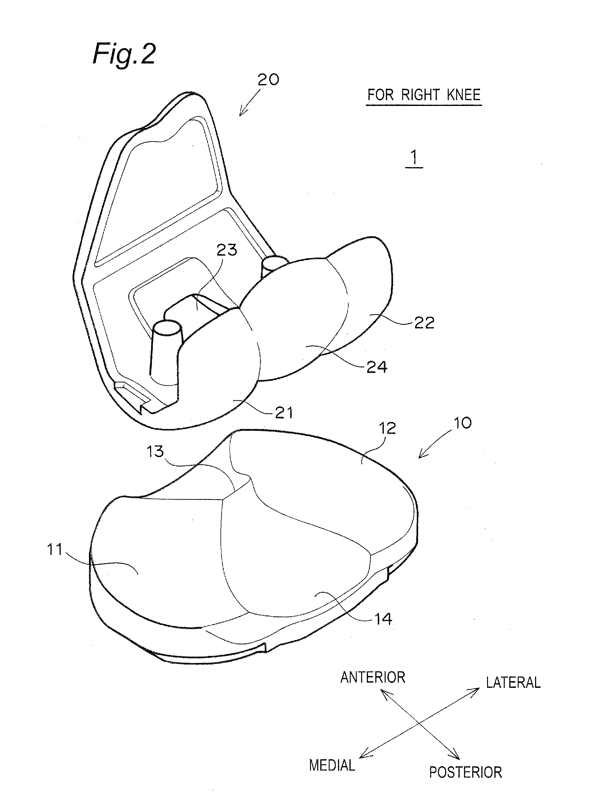
[0071]FIGS. 1 and 2 show an artificial knee joint 1 in the present embodiment.

[0072]The artificial knee joint 1 includes a femoral component 20 fixed to a distal end of a femur, and a tibial plate 10 fixed to a proximal end of a tibia.

[0073]The femoral component 20 includes a medial condyle 21 and a lateral condyle 22. Between the medial condyle 21 and the lateral condyle 22 are formed an opening 23 and an elliptical spherical sliding portion 24 for connecting posterior ends of the medial condyle 21 and the lateral condyle 22.

[0074]The tibial plate 10 is fixed to the proximal end of the tibia via a metal tibial tray (not shown). The tibial plate 10 includes a medial fossa 11 and a lateral fossa 12. A spine 13 and a concave sliding surface 14 forming the posterior surface of the spine 13 are formed between the medial fossa 11 and the lateral fossa 12.

[0075]When the femoral component 20 and the tibial plate 10 form the artificial knee joint 1, the medial condyle 21 of the femoral comp...

second embodiment

[0118]The artificial knee joint 1 of the present embodiment can externally rotate more easily in flexion. This embodiment differs from the first embodiment in the shape of an edge on the posterior end side of the tibial plate 10. The structures of other components in the present embodiment are the same as those of the first embodiment.

[0119]In the present embodiment, in order to promote the external rotation of the knee joint in deep flexion, the tibial plate 10 preferably includes a posterior end sliding surface at the edge of the posterior end side of the lateral fossa 12.

[0120]In the present embodiment, as shown in FIG. 15, the posterior end of the lateral fossa 12 of the tibial plate 10 is preferably chamfered by a plane or a curved surface. The chamfered surface forms a posterior end sliding surface (posterior end sliding curved surface 12c, or posterior end sliding plane 12p).

[0121]The term “posterior end sliding curved surface 12c” as used in the present specification means a...


PUM


Abstract

An artificial knee joint comprises a femoral component a tibial plate slidably receive the femoral component. The femoral component includes medial and lateral condyles, an opening and an elliptical spherical sliding portion are formed therebetween. The elliptical spherical sliding portion couples posterior ends of the medial and lateral condyles, and slides with respect to the tibial plate when flexing the knee joint. The tibial plate includes a medial fossa and a lateral fossa, and a spine and a concave sliding surface are formed therebetween. The spine moves within the opening in an antero-posterior direction in response to flexion-extension action of the knee joint, and comes into contact with the sliding portion when flexing. The concave sliding surface forms a posterior surface of the spine, and slidably receives the elliptical spherical portion. A width of the elliptical spherical sliding portion is widened from the opening toward a posterior end.

Description

TECHNICAL FIELD[0001]The present invention relates to artificial knee joints, and more particularly, to an artificial knee joint whose rotation resistance can be controlled according to a flexion angle. The present artificial knee joint can have high stability in the antero-posterior direction and can also reduce local wear of a post.BACKGROUND ART[0002]When the knee joint is deformed seriously due to a degenerative knee joint disease or a chronic rheumatism, a replacement surgery of an artificial knee joint is performed to restore the normal function of the knee joint.[0003]The artificial knee joint includes a femoral component fixed to a distal end of a femur, and a tibial component fixed to a proximal end of a tibia (see, for example, Patent Documents 1 to 3). The tibial component includes a tibial tray made of metal, ceramic, or resin directly fixed to the tibia, and a resin tibial plate fixed to an upper surface of the tibial tray in contact with the femoral component.[0004]In ...

Claims


Application Information

Patent Timeline
IPC IPC(8): A61F2/38
CPCA61F2/3836A61F2/3886A61F2/30A61F2/38
Inventor HASHIDA, MASAHIKO
Owner KYOCERA MEDICAL CORP
Why Eureka
Try Eureka