Control unit for construction machine

a technology for controlling units and construction machines, applied in the direction of electric control, speed sensing governors, instruments, etc., can solve problems such as the difference in engine speed response, and achieve the effect of good operating feeling

Active Publication Date: 2013-07-25
HITACHI CONSTR MASCH CO LTD
View PDF0 Cites 12 Cited by
  • Summary
  • Abstract
  • Description
  • Claims
  • Application Information

AI Technical Summary

Benefits of technology

[0012]In the aspect of the present invention, lug-down can be lightened even with reduction in the engine output that may occur

Problems solved by technology

Such a problem arises from a difference in response between the engine speed and a capacity of a hydrauli

Method used


Image

  • Control unit for construction machine
  • Control unit for construction machine
  • Control unit for construction machine

Examples


Embodiment Construction

[0018]An embodiment of the present invention will be described below with reference to the accompanying drawings.

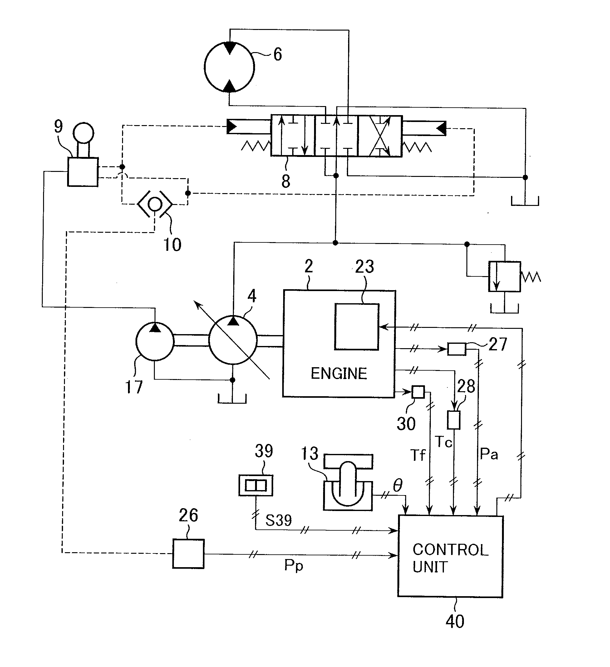
[0019]FIG. 1 is a configuration diagram showing schematically a construction machine according to an embodiment of the present invention. The construction machine shown in this figure includes an engine 2 (diesel engine) 2, a hydraulic pump 4, an auxiliary hydraulic pump 17, a hydraulic actuator 6, a directional control valve 8, a control lever (operating device) 9, a pressure sensor 27, a temperature sensor 28, a temperature sensor 30 (detecting means), an engine control dial (speed input means) 13, and a control unit 40. Specifically, the engine 2 is what is called an electronic control type. The hydraulic pump 4, a variable displacement type, is mechanically connected to an output shaft of the engine 2 and driven by the engine 2. The auxiliary hydraulic pump 17 is driven by the engine 2. The hydraulic actuator 6 is driven by hydraulic fluid delivered from the hydraulic...


PUM


Abstract

A target speed setting section sets a target speed of an engine to an idle speed that is lower than an input speed with an engine control dial when no operating signal is output from a control lever over a predetermined period of time. A speed control section controls the speed of the engine based on the target speed set by the target speed setting section, which includes an idle speed setting section that corrects the idle speed according to values detected by sensors so that reduction in an output of the engine due to a change in a state quantity associated with an environment under which the engine is placed can be inhibited. This allows a good operating condition to be achieved during a reset from an auto idle state even with an engine output has been reduced according to a change in environment.

Description

TECHNICAL FIELD[0001]The present invention relates to a control unit for a construction machine that controls to reduce an engine speed to an idle speed when an operating device is placed in a neutral position.BACKGROUND ART[0002]In general, construction machines, such as hydraulic excavators, incorporate a speed input device (e.g. an engine control dial) that is used to direct speed of an engine (diesel engine). An operator operates the speed input device to thereby set a target speed for the engine. In such a construction machine, control (auto idle control) is performed so as to set the engine speed to a value (idle speed) smaller than the speed directed by the speed input device when a predetermined period of time elapses after all of operating devices (control levers) that direct operation of a hydraulic actuator (a driven member) are held in neutral positions. Reduction in fuel consumption (hereinafter may be referred to as fuel efficiency) or noise, for example, is thereby ac...

Claims


Application Information

Patent Timeline
IPC IPC(8): E02F9/20
CPCF02D29/00F02D31/008F02D41/021E02F9/2062F02D2200/023F02D2200/0414F02D2200/0606F02D41/083F02D29/04F02D45/00
Inventor NARAZAKI, AKIHIROKARASAWA, HIDEONAKAMURA, TSUYOSHI
Owner HITACHI CONSTR MASCH CO LTD
Why Eureka
Try Eureka