Toilet apparatus

Inactive Publication Date: 2013-08-01
LIXIL CORP
View PDF0 Cites 8 Cited by
  • Summary
  • Abstract
  • Description
  • Claims
  • Application Information

AI Technical Summary

Benefits of technology

[0020]The discharge part is normally closed by the closing tool in the toilet apparatus. The blower is driven while the discharge part is closed by the closing tool in the toilet apparatus, with the result that air in a toilet can be discharged via the toilet bowl and the air flow path. More specifically, the toilet apparatus can discharge odor in the toilet. Furthermore, the toilet apparatus can also discharge via the air flow path odor emitted from waste or the like while receiving the waste or the like on the receiving member. Consequently, the user can hardly smell the odor emitted from the waste or the like (foul odor) and diffusion of the odor in the toilet can be suppressed. Furthermore, a time period in which the discharge part is kept open is short since the closing tool opens the discharge part when the weight of waste or the like received by the receiving member exceeds a set weight or when the waste or the like having fallen onto the receiving member is detected, and the closing tool closes the discharge part when the waste or the like has fallen from the receiving member. Accordingly, an amount of odor in the waste collection tub

Problems solved by technology

This results in foul odor rising from the waste collection tub.
It is difficult to exhaus

Method used


Image

  • Toilet apparatus
  • Toilet apparatus
  • Toilet apparatus

Examples


embodiment 1

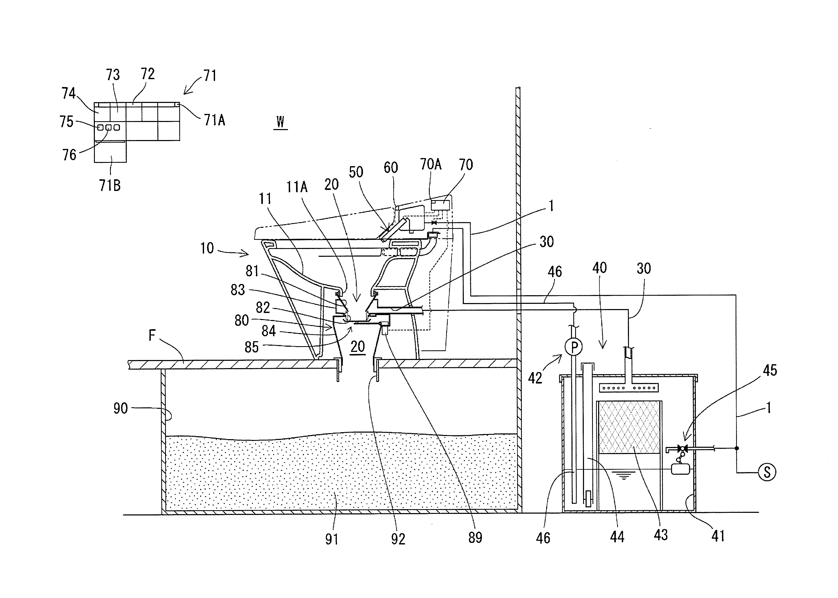
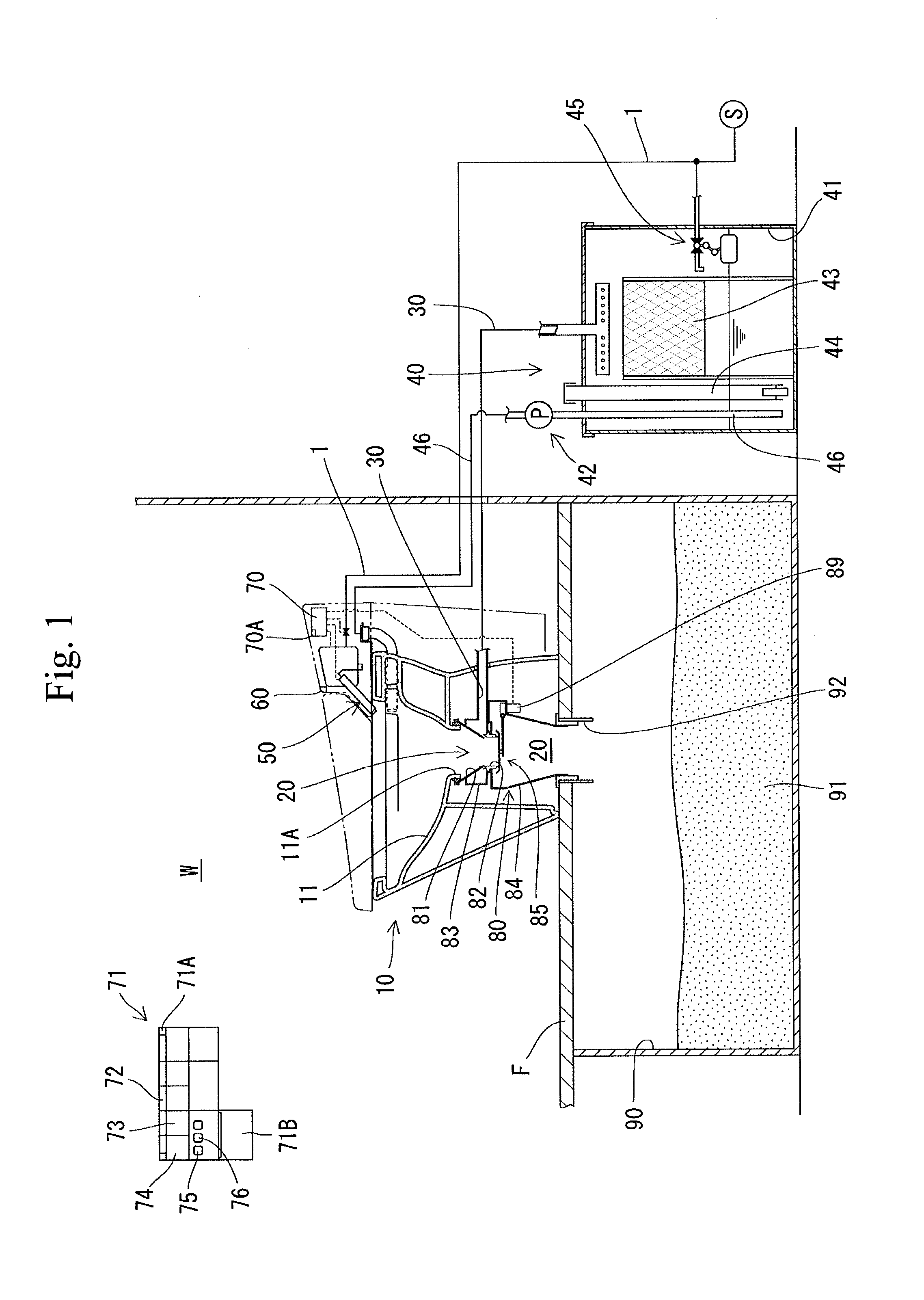
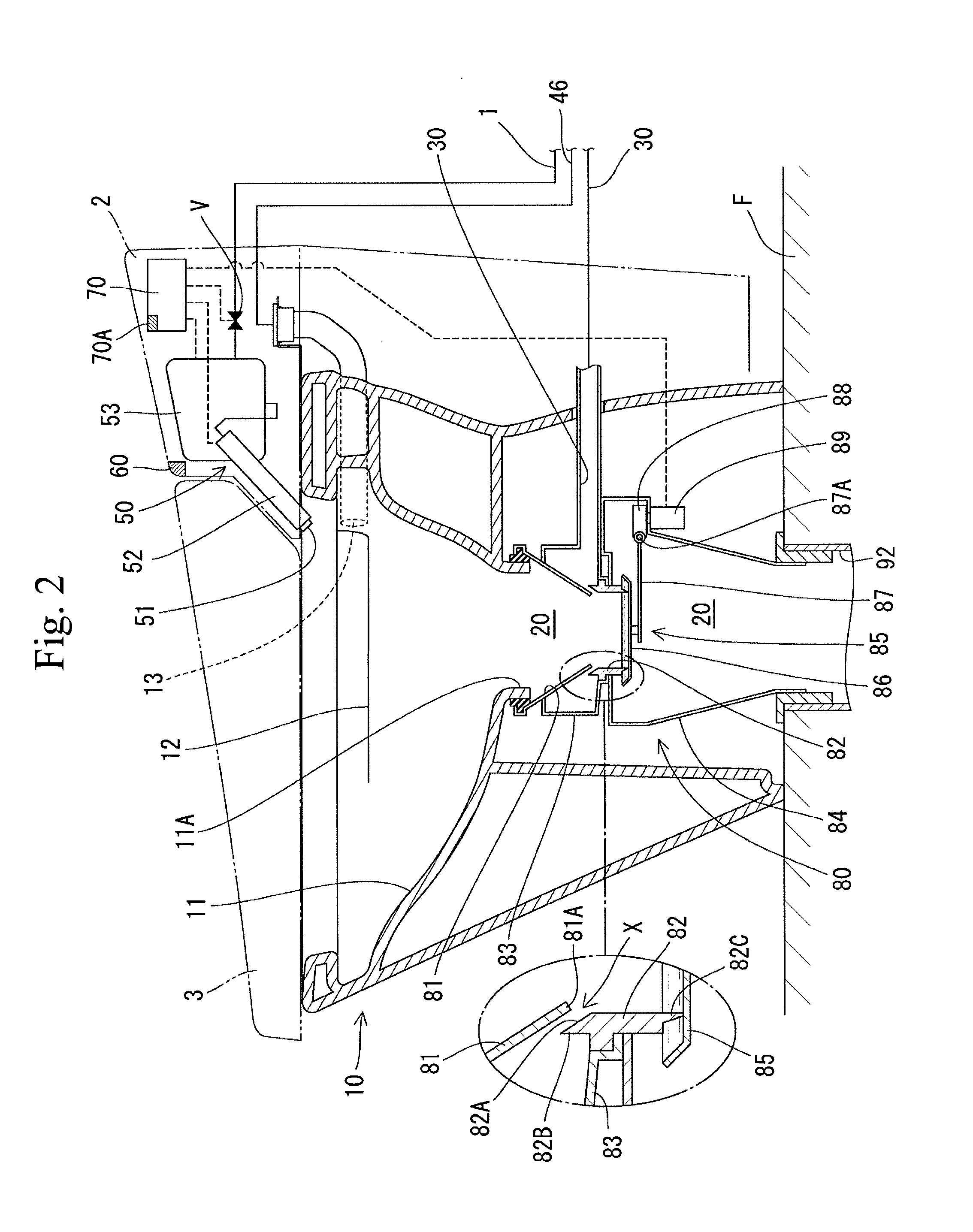
[0053]A toilet apparatus of embodiment 1 includes a toilet body 10, a discharge part 20, a drainage channel 30, a toilet flushing device 40, a private parts cleaning device 50, a detecting device 60, a control device 70 and a connecting device 80.

[0054]The toilet body 10 is provided with a toilet bowl 11 having a drain outlet 11A in a lower part thereof. The toilet bowl 11 has a rim water passage 12 formed along an upper inner periphery of the toilet bowl 11 so that flush water discharged from a rim discharge conduit 13 flows along the upper inner periphery of the toilet bowl 11. Since flush water flowing through the rim water passage 12 steadily flows downward along an inner surface of the toilet bowl 11, an entire inner surface of the toilet bowl can be flushed by flush water.

[0055]The connecting device 80 is connected to the drain outlet 11A of the toilet bowl 11. The connecting device 80 forms the discharge part 20 communicating the drain outlet 11A to a waste collection tub 90 ...

embodiment 2

[0112]The toilet apparatus according to embodiment 2 differs from embodiment 1 in that when the private parts cleaning water ejected from the cleaning nozzle 51 by actuation of the private parts cleaning device 50 equals or exceeds the set amount in the private parts cleaning operation, the toilet flushing device 40 is actuated to supply a set amount of flush water to the toilet bowl 11 before the private parts cleaning water flowing into the toilet bowl 11 is caused to flow into the drainage channel 30 (step S21), as shown in FIG. 10. The other construction of the toilet apparatus according to embodiment 2 is the same as that of embodiment 1. Identical or similar parts in embodiment 2 are labeled by the same reference symbols as those in embodiment 1 and detailed description of these parts will be eliminated.

[0113]In the private parts cleaning operation, when the user presses the private parts cleaning-button 73 of the remote controller 71 (step S6), the private parts cleaning devi...

embodiment 3

[0132]The toilet apparatus of embodiment 3 includes the toilet bowl 11, the discharge part 20, the closing tool 85, an air flow path 100 and a fan 110 serving as the blower, as shown in FIG. 11. The toilet bowl 11 is provided in the toilet body 10 and is upwardly open. The toilet bowl 11 has a drain outlet 11A formed through the lowermost end thereof. The toilet body 10 has the toilet cover 3 and the toilet seat 4 both provided above the toilet bowl 11.

[0133]The toilet body 10 is installed on a floor surface F in the toilet room. The waste collection tub 90 is provided below the floor surface F. The floor surface F has a through hole 92 located below the drain outlet 11A of the toilet bowl 11. The connecting device 80 which will be described later has a lower end that is inserted into the hole 92 thereby to be connected to the floor. The waste collection tub 90 can store waste F falling through the hole 92.

[0134]The connecting device 80 is connected to the drain outlet 11A of the to...


PUM


Abstract

Providing a toilet apparatus which can reduce an amount of water discharged into a waste collection tub. The toilet apparatus includes a toilet body (10) equipped with a toilet bowl (11) having a drain outlet (11A) in its lower part, a discharge part (20) communicating between the drain outlet (11A) and a waste collection tub (90) located below the toilet body (10), a drainage channel (30) branched from the discharge part (20), and a private parts cleaning device (50) assembled to the toilet body (10) and having a cleaning nozzle (51). When the private parts cleaning device (50) is actuated and an amount of cleaning water ejected from the cleaning nozzle (51) equals or exceeds a set amount, the cleaning water flowing into the toilet bowl (11) is caused to flow into the drainage channel (30) without being discharged via the discharge part (20) into the waste collection tub (90).

Description

TECHNICAL FIELD[0001]The present invention relates to a toilet apparatus.BACKGROUND ART[0002]Patent Document 1 discloses a conventional toilet apparatus. The disclosed toilet apparatus includes a toilet body provided with a toilet bowl having a drain outlet in a lower part thereof, a discharge part communicating the outlet to a waste collection tub located below the toilet body, a drainage channel branched off from the discharge part, a toilet flushing device supplying flush water to the toilet bowl and a detecting device which detects a user of the toilet body.[0003]In this toilet apparatus, after the detecting device has ceased detecting the user, a small amount of flush water is firstly supplied into the toilet bowl by the toilet flushing device so that toilet paper or the like remaining in the toilet bowl is caused to flow into the waste collection tub with the flush water. A large amount of flush water is subsequently supplied into the toilet bowl to flush the toilet bowl. In t...

Claims


Application Information

Patent Timeline
IPC IPC(8): E03D9/08
CPCE03D9/08E03D5/016E03D5/012E03D1/00
Inventor IMAI, SHIGEONAKAMIYA, TOSHIHIROMURAI, TATSUNORI
Owner LIXIL CORP
Why Eureka
Try Eureka