Turbine shroud hanger with debris filter

a technology for turbine shrouds and filters, which is applied in the manufacture of engines, engine components, machines/engines, etc., can solve the problems of small air passages not being able to deliver air to the turbine shrouds, significant damage or destruction of the shrouds

Inactive Publication Date: 2013-08-01
GENERAL ELECTRIC CO
View PDF4 Cites 40 Cited by
  • Summary
  • Abstract
  • Description
  • Claims
  • Application Information

AI Technical Summary

Benefits of technology

[0006]According to one embodiment of the invention, a turbine shroud hanger apparatus for a gas turbine engine includes: (a) an arcuate shroud hanger having at least one cooling hole passing therethrough, the cooling hole having an inlet and an outlet; and (b) a filter carried by the...

Problems solved by technology

When sufficiently plugged, these small air passages will not deliver air to the turbine shr...

Method used


Image

  • Turbine shroud hanger with debris filter
  • Turbine shroud hanger with debris filter
  • Turbine shroud hanger with debris filter

Examples


Embodiment Construction

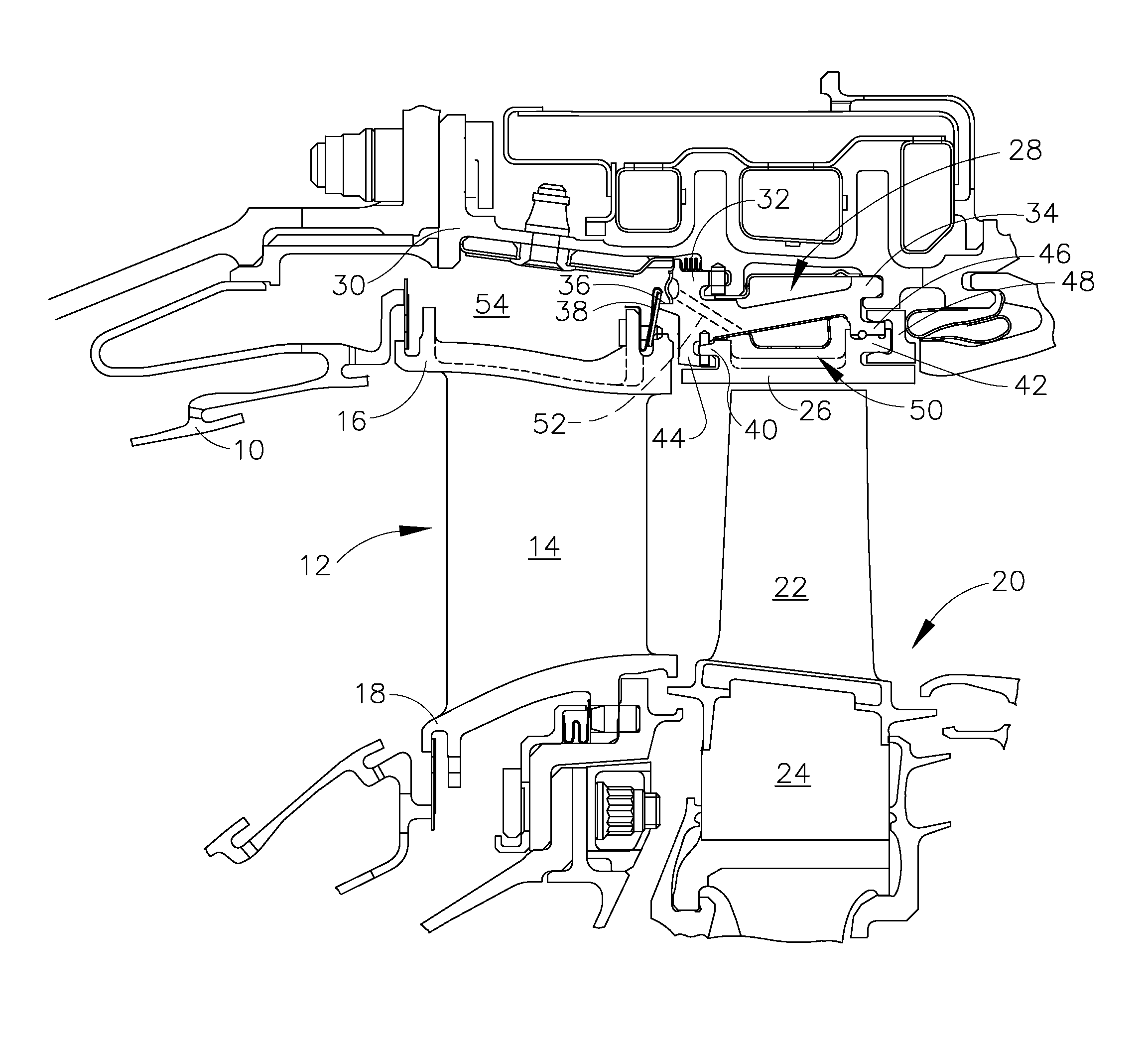
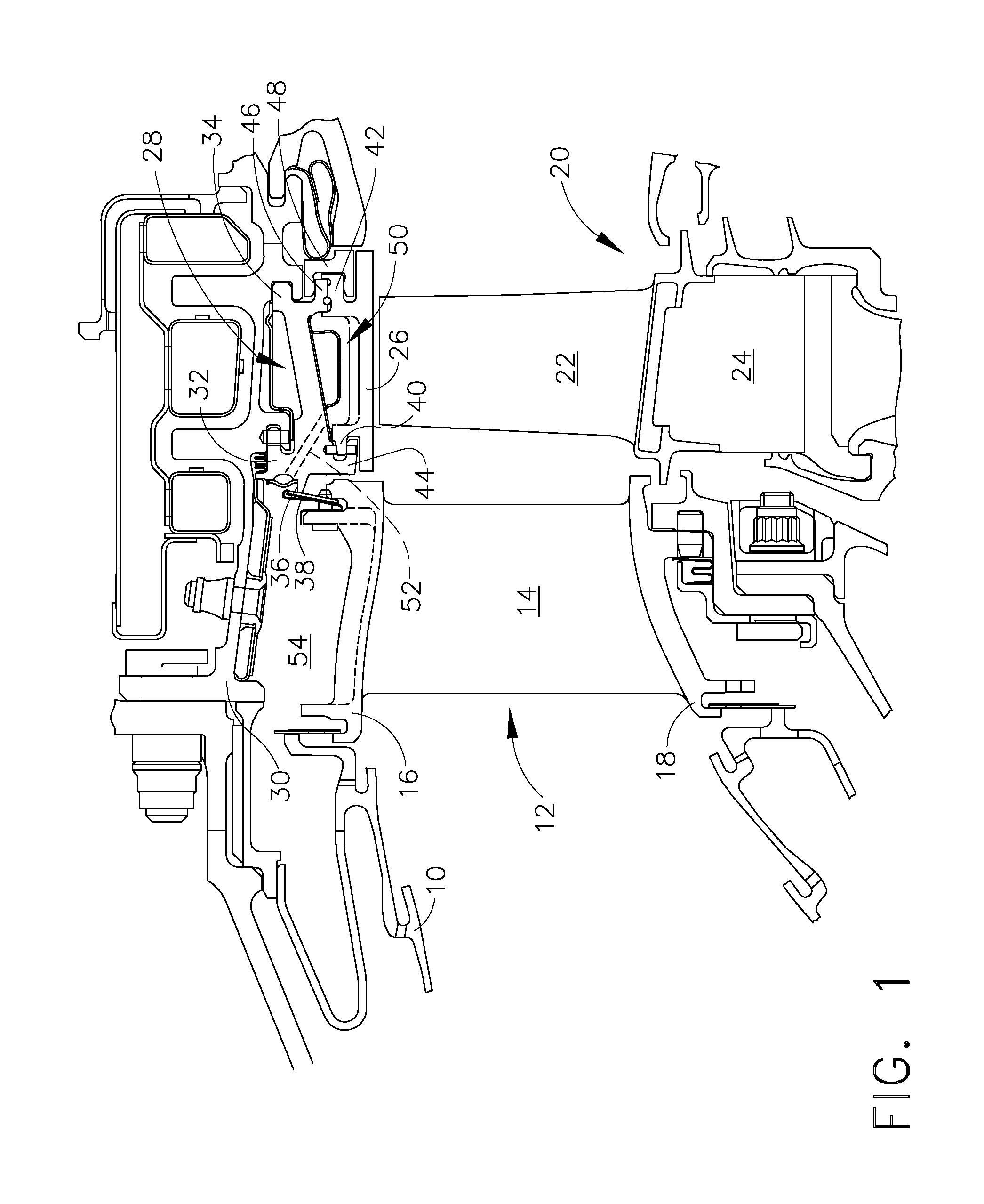
[0014]Referring to the drawings wherein identical reference numerals denote the same elements throughout the various views, FIG. 1 depicts a portion of a high pressure turbine, which is part of a gas turbine engine of a known type. The function of the high pressure turbine is to extract energy from high-temperature, pressurized combustion gases from an upstream combustor 10 and to convert the energy to mechanical work, in a known manner. The high pressure turbine drives an upstream compressor (not shown) through a shaft so as to supply pressurized air to the combustor 10.

[0015]In the illustrated example, the engine is a turbofan engine and a low-pressure turbine would be located downstream of the high pressure turbine 10 and coupled to a shaft driving a fan and optionally a low-pressure compressor or “booster”. However, the principles described herein are equally applicable to turboprop, turbojet, and turboshaft engines, as well as turbine engines used for other vehicles or in stati...


PUM


Abstract

A turbine shroud hanger apparatus for a gas turbine engine includes: an arcuate shroud hanger having at least one cooling hole passing therethrough, the cooling hole having an inlet and an outlet; and a filter carried by the shroud hanger positioned upstream of the inlet of the cooling hole, the filter having a plurality of openings formed therethrough which are sized to permit air flow through the cooling hole while preventing the entry of debris particles larger than a preselected size into the cooling hole.

Description

CROSS REFERENCE TO RELATED APPLICATIONS[0001]This is a national stage application under 35 U.S.C. §371(c) of prior-filed, co-pending PCT patent application serial number PCT / US2011 / 028294, filed on Mar. 14, 2011, which claims priority to Polish Patent Application Serial No. P-390758, filed on Mar. 18, 2010, the entire contents of which are incorporated herein by reference.BACKGROUND OF THE INVENTION[0002]Embodiments of this invention relate generally to gas turbine engines, and more particularly to apparatus for preventing obstruction of cooling holes in the turbine sections of such engines.[0003]A typical gas turbine engine includes a turbomachinery core having a high pressure compressor, a combustor, and a high pressure turbine in serial flow relationship. The core is operable in a known manner to generate a primary gas flow. The high pressure turbine includes one or more rotors which extract energy from the primary gas flow. Each rotor comprises an annular array of blades or buck...

Claims


Application Information

Patent Timeline
IPC IPC(8): F02C7/20
CPCF01D11/08F01D25/14F01D25/24F01D25/246F05D2260/607F02C7/20F05D2260/201F05D2230/232F05D2230/237F05D2250/711F05D2250/30
Inventor HORINE, BENJAMIN MARSHALLMICHALCZUK, JACEKPILAT, MIROSLAW
Owner GENERAL ELECTRIC CO
Why Eureka
Try Eureka