Phosphor placement in white light emitting diode assemblies

a technology of light-emitting diodes and phosphors, which is applied in the direction of semiconductor/solid-state device manufacturing, electrical apparatus, semiconductor devices, etc., can solve the problems achieve the effects of reducing the likelihood of interabsorption, promoting heat removal, and low conversion efficiency

Active Publication Date: 2013-08-01
BRIDGELUX INC
View PDF0 Cites 28 Cited by
  • Summary
  • Abstract
  • Description
  • Claims
  • Application Information

AI Technical Summary

Benefits of technology

[0014]The first phosphor material has a relatively low conversion efficiency as compared to the conversion efficiency of the second phosphor material. Placement of the first and second luminescent materials in the white LED assembly promotes removal of heat from the inefficient first phosphor material and reduces the likelihood of interabsorption.

Problems solved by technology

Placement of the first and second luminescent materials in the white LED assembly promotes removal of heat from the inefficient first phosphor material and reduces the likelihood of interabsorption.

Method used


Image

  • Phosphor placement in white light emitting diode assemblies
  • Phosphor placement in white light emitting diode assemblies
  • Phosphor placement in white light emitting diode assemblies

Examples


Embodiment Construction

[0037]Reference will now be made in detail to some embodiments of the invention, examples of which are illustrated in the accompanying drawings. In the description and claims below, when a first object is referred to as being disposed “on” a second object, it is to be understood that the first object can be directly on the second object, or an intervening object may be present between the first and second objects. Similarly, terms such as “above”, “beneath”, “lateral”, “vertical”, upper”, and “lower” are used herein to describe relative orientations between different parts of the white LED assembly structure being described, and it is to be understood that the overall white LED assembly being described can actually be oriented in any way in three-dimensional space.

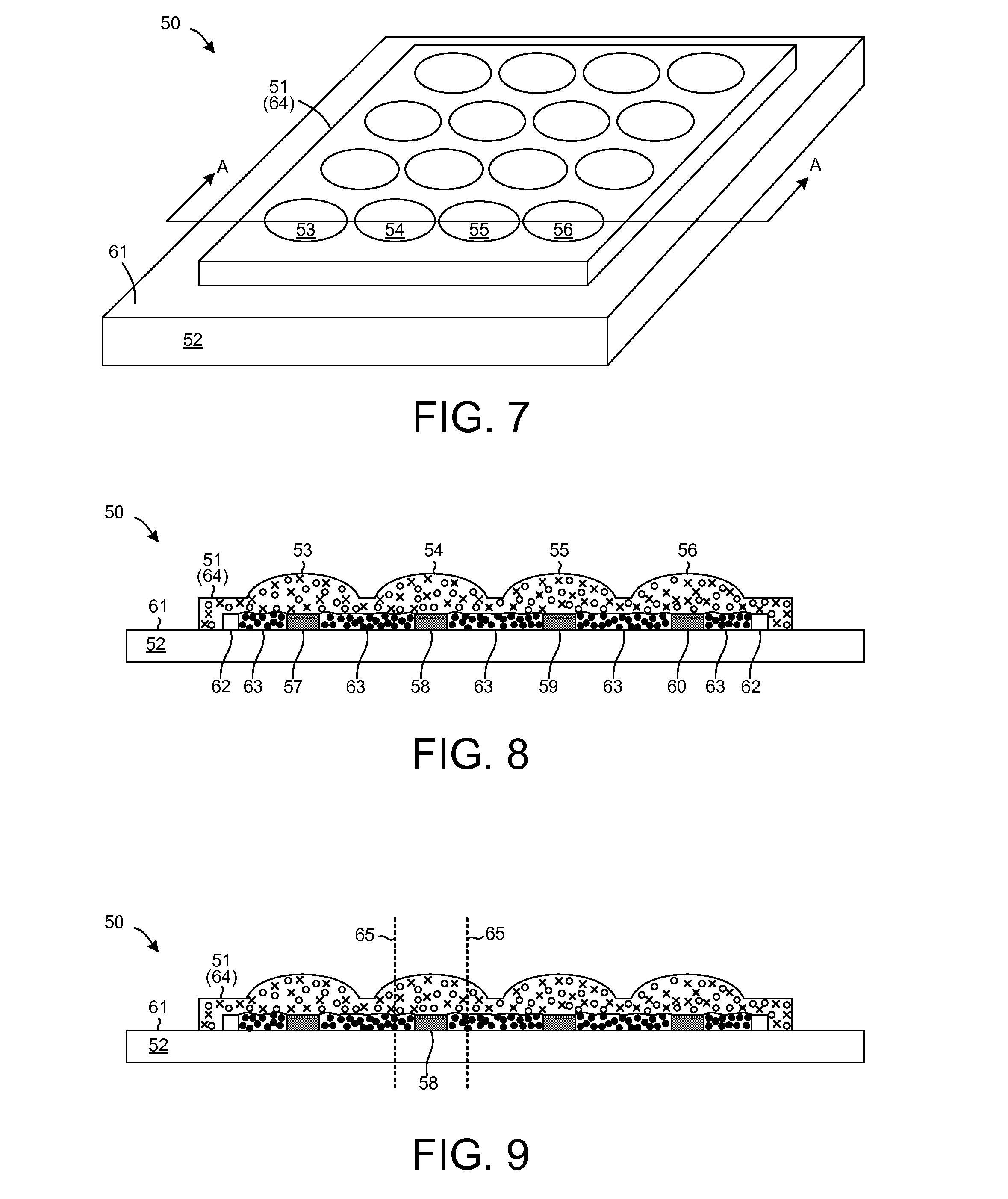
[0038]FIG. 7 is a simplified perspective diagram of a white LED assembly 50 in accordance with one novel aspect. A molded two-dimensional array 51 of dome-shaped mini-lens structures is disposed on a square substrate 52. R...


PUM


Abstract

A white LED assembly includes a blue LED die attached to a substrate. A first volume of a first luminescent material surrounds the blue LED die in a lateral dimension such that none of the first luminescent material is disposed directly over the blue LED die. The first luminescent material includes a relatively inefficient phosphor having a peak emission wavelength longer than 620 nm and includes substantially no phosphor having a peak emission wavelength shorter than 620 nm. A second volume of a second luminescent material is disposed over the first volume and the blue LED die. The second luminescent material includes a relatively efficient phosphor having a peak emission wavelength shorter than 620 nm and includes substantially no phosphor having a peak emission wavelength longer than 620 nm. Placement of the first and second luminescent materials in this way promotes removal of heat from the inefficient phosphor and reduces the likelihood of interabsorption.

Description

TECHNICAL FIELD[0001]The present disclosure relates generally to white LED (Light Emitting Diode) assemblies.BACKGROUND INFORMATION[0002]A so-called white Light Emitting Diode (LED) is a solid state device that converts electrical energy into light. FIG. 1 (Prior Art) is a simplified cross-sectional diagram of a white LED assembly 1. The white LED assembly is actually an assembly that includes a blue light emitting diode (LED) die 2, commonly referred to as a blue LED. The active region 3 within the blue LED die is an InGaN / GaN Multiple Quantum Well (MQW) structure. The blue LED die therefore emits relatively narrowband blue light having a wavelength in a range from 455 nanometers (nm) to about 455 nm. Blue LED die 2 is mounted in a reflector cup of a substrate 4. In addition to blue LED die 2 and substrate 4, the white LED assembly 1 includes an amount of luminescent material 5. Luminescent material 5 includes phosphor particles and a transparent binding material. The luminescent m...

Claims


Application Information

Patent Timeline
Patent Type & Authority Applications(United States)
IPC IPC(8): H01L33/50
CPCH01L25/0753H01L33/504H01L33/505H01L2933/0041H01L2224/48137H01L2224/48091H01L2924/00H01L2924/00014
Inventor XU, TAOGAN, ZHENGQING
Owner BRIDGELUX INC
Why Eureka
Try Eureka