
Differential amplifier circuit with ultralow power consumption provided with adaptive bias current generator circuit

Active Publication Date: 2013-08-01
SONY CORP
View PDF1 Cites 12 Cited by
  • Summary
  • Abstract
  • Description
  • Claims
  • Application Information

AI Technical Summary

Benefits of technology

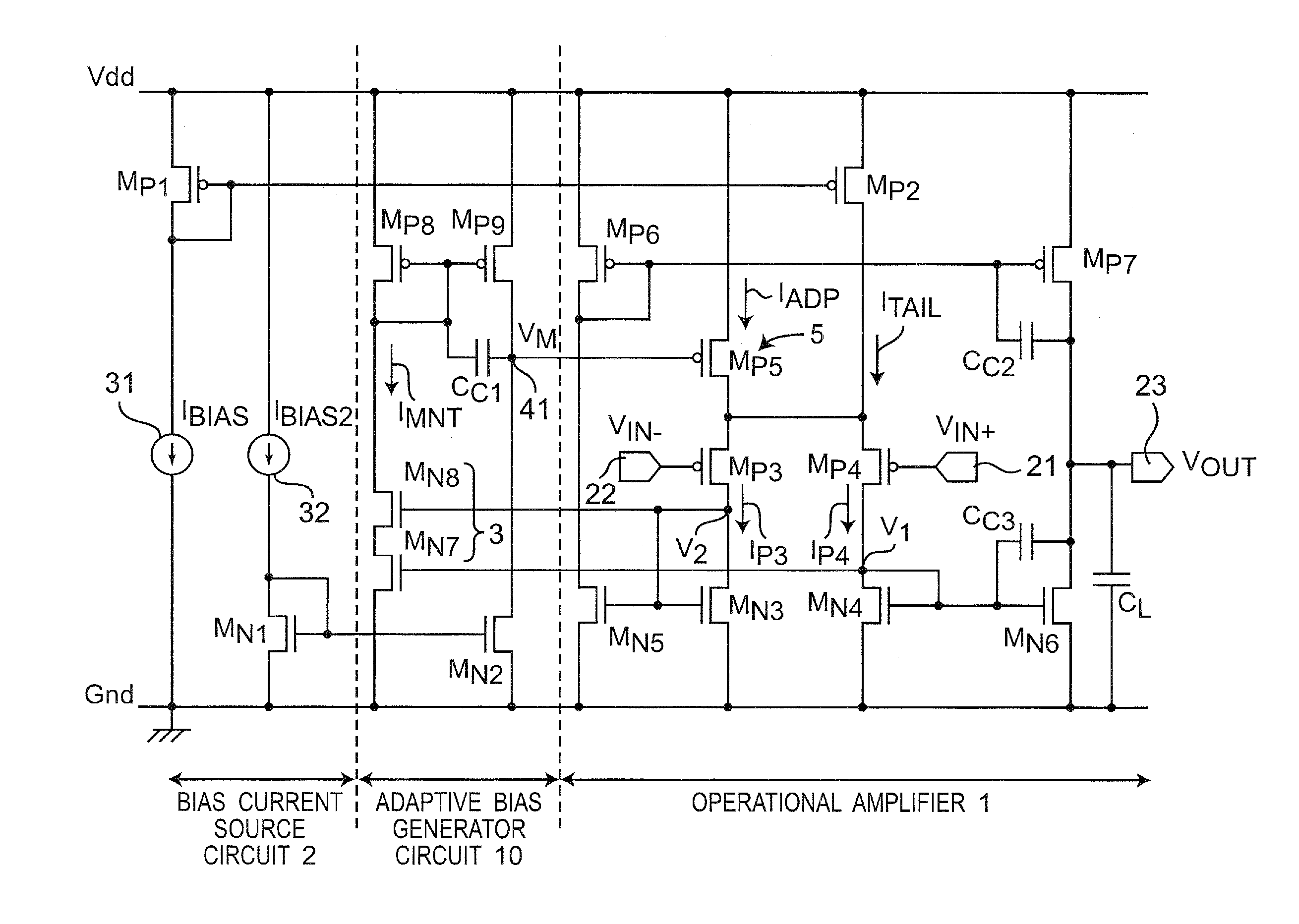
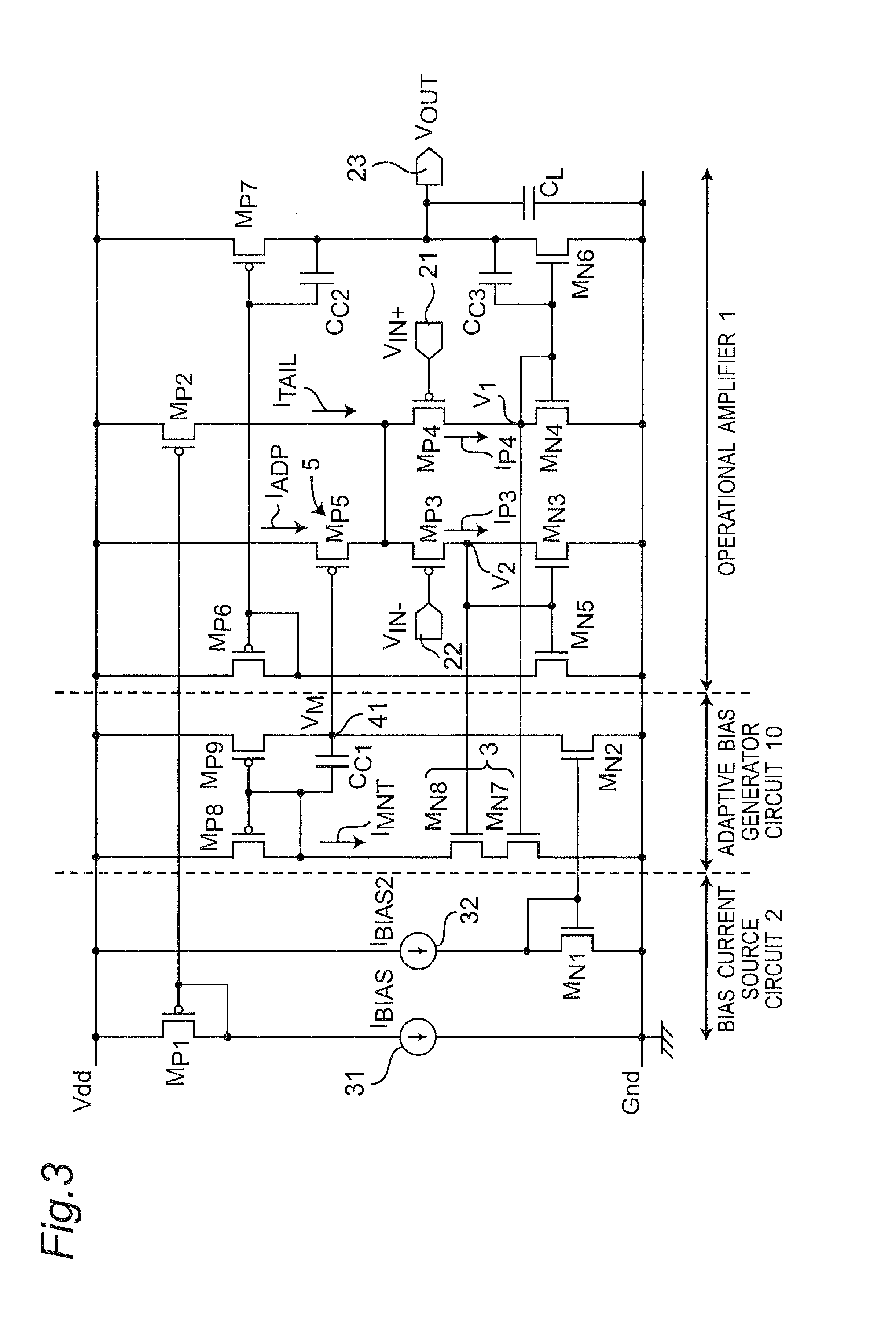
This patent is about a new circuit that solves problems of slow operation and high power consumption in previous differential amplifier circuits. The circuit uses a bias current generator that monitors two input voltages and controls an adaptive bias current with the negative feedback configuration of the differential pair circuit and the bias current generator circuit. This results in high-speed and low power consumption operation.

Problems solved by technology

However, the operational amplifier circuit of ultralow power operation has had such a problem that its response time was increased due to the collapse of the virtual grounding caused by an input change ascribed to deterioration in the driving capability due to a minute current bias.
However, there is the problem of difficulty in generating a large adaptive bias current in the proposed system, which leads to a failure in making the operational amplifier have high speed.

Method used


Image

  • Differential amplifier circuit with ultralow power consumption provided with adaptive bias current generator circuit
  • Differential amplifier circuit with ultralow power consumption provided with adaptive bias current generator circuit
  • Differential amplifier circuit with ultralow power consumption provided with adaptive bias current generator circuit

Examples


Embodiment Construction

[0050]Preferred embodiments of the present invention will be described below with reference to the drawings. In the following preferred embodiments, like components are denoted by like reference numerals.

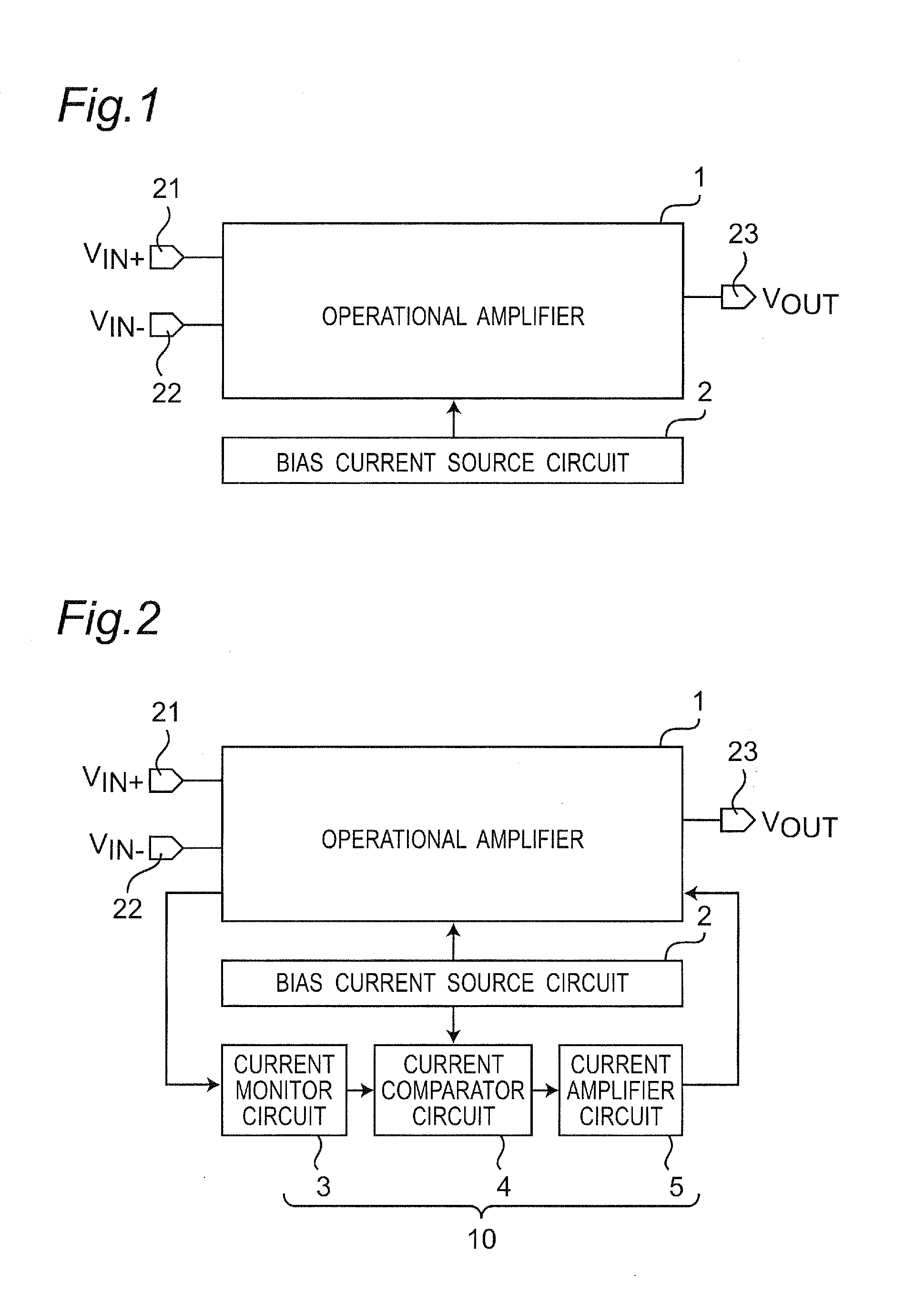
[0051]In the preferred embodiments of the present invention, adaptive bias current generator circuits based on a novel architecture are proposed. Moreover, operational amplifiers that use this and achieve high speed and low power consumption are proposed. The operational amplifier circuit of the present preferred embodiment monitors a current flowing through the input differential pair circuit of the operational amplifier, and compares this with a bias current. By generating an adaptive bias current on the basis of a comparison result, the high-speed operation of the operational amplifier is achieved. The configurations of the preferred embodiments and their modified preferred embodiments and the details of simulation evaluation results are described below.

[0052]FIG. 2 is a block di...


PUM


Abstract

A differential amplifier circuit includes a differential operational amplifier that includes a differential pair circuit and operates based on a constant bias current supplied from a bias current source circuit, and the differential amplifier circuit includes a bias current generator circuit. A current monitor circuit detects two currents flowing through the differential pair circuit in correspondence with differential input voltages inputted to the differential pair circuit, and detect a minimum current of the two currents for a difference voltage of the differential input voltages as a monitored current. A current comparator circuit compares the monitored current with the constant bias current. A current amplifier circuit amplifies a voltage corresponding to the comparison result, and controls currents flowing through the differential pair circuit based on an amplified voltage, and the bias current generator circuit performs negative feedback adaptive control such that the bias current increases as the monitored current decreases.

Description

BACKGROUND OF THE INVENTION[0001]1. Field of the Invention[0002]The present invention relates to an ultralow power differential amplifier circuit that uses an adaptive bias current generator circuit.[0003]2. Description of the Related Art[0004]Sub-threshold LSIs utilizing the sub-threshold region operation of MOSFETs attract attention in order to actualize LSIs of ultralow consumption power. However, since this design method is in the initial stage of development, it is strongly demanded to establish a design technology of an ultralow power consumption circuit. Up to now, various researches have been conducted to actualize ultralow power LSIs (See, for example, a Non-Patent Document 1).[0005]A differential amplifier circuit is one of basic analog component circuits and is a component circuit of high versatility to achieve various analog operation functions. An operational amplifier, which is one differential amplifier circuits, is used in a negative feedback configuration and operat...

Claims


Application Information

Patent Timeline
IPC IPC(8): H03F3/45
CPCH03F3/45179H03F1/0261H03F3/3028H03F2203/45626H03F2203/30021H03F2203/45244H03F2203/45454H03F3/45183
Inventor HIROSE, TETSUYAOSAKI, YUJITSURUYA, YUMIKOKOBAYASHI, OSAMU
Owner SONY CORP
Learn More