Multiple concentric wound film capacitors

a wound film capacitor and concentric technology, applied in wound capacitors, variable capacitors, fixed capacitors, etc., can solve the problems of increased weight, poor high frequency response, and potential oil rupture, and achieve the effect of improving the high frequency response, mounting restrictions, and increasing weigh

Active Publication Date: 2013-08-01
ELECTRONICS CONCEPTS
View PDF7 Cites 20 Cited by
  • Summary
  • Abstract
  • Description
  • Claims
  • Application Information

AI Technical Summary

Benefits of technology

[0028]an end of the conductive rod includes a thermally conductive stud extending through a wall of the enclosure for mounting the enclosure onto an external thermally conductive surface. The conductive rod and the conduc

Problems solved by technology

Capacitors using this type of technology, however, have problems of potential oil rupture, expensive housings and terminals, poor high frequency response (noisy), mounting restrictions and increased weight.
These capacitors are permanently disconnected from the circuit and cannot be reset.
Dry film capacitors, however, have a failure mode that is typically not found in oil fill capacitors.
This failure mode is caused by the quality of the capacitor and its electrode configuration which does not allow the capacitor to go to a low resistance short.
This, in turn, causes further healing and leads to an avalanching affect.
Eventually the capacitor goes to a high resistance short of several ohms, whic

Method used


Image

  • Multiple concentric wound film capacitors
  • Multiple concentric wound film capacitors
  • Multiple concentric wound film capacitors

Examples


Embodiment Construction

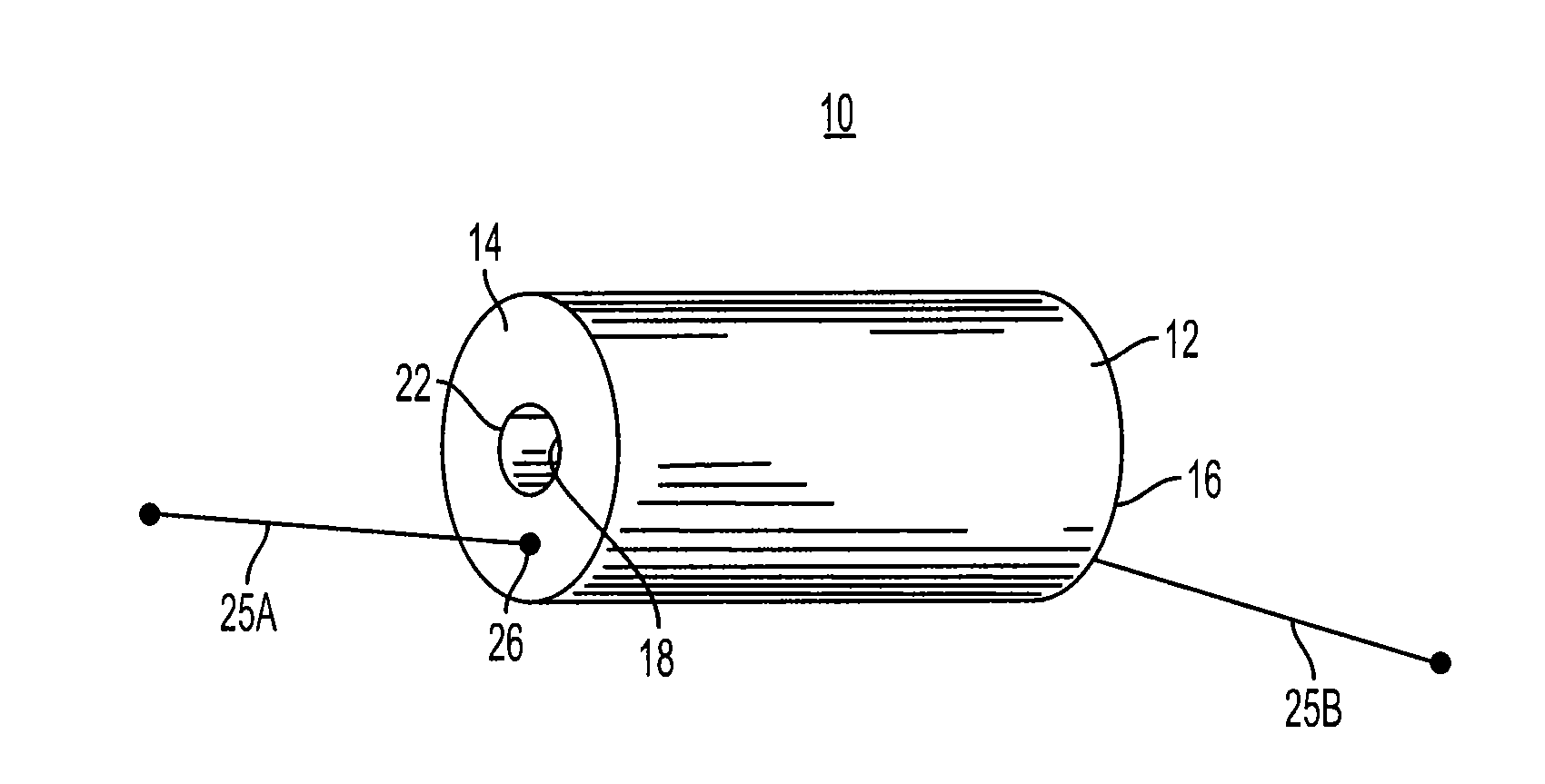
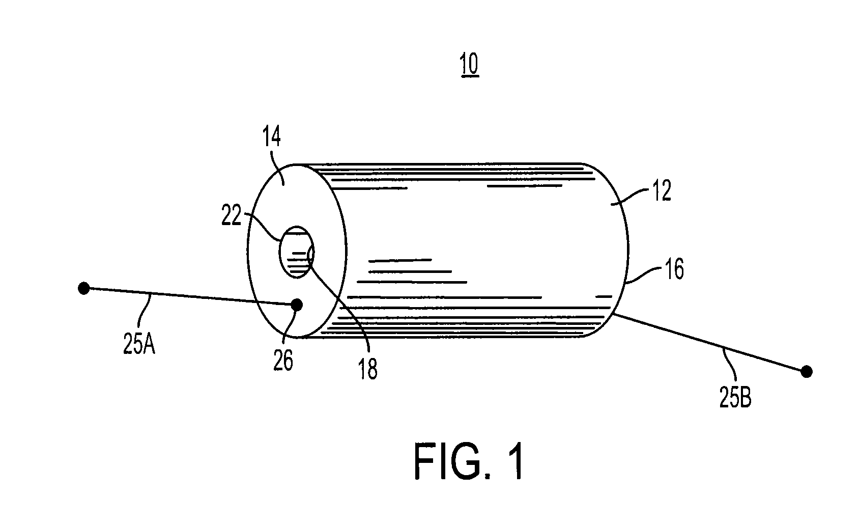
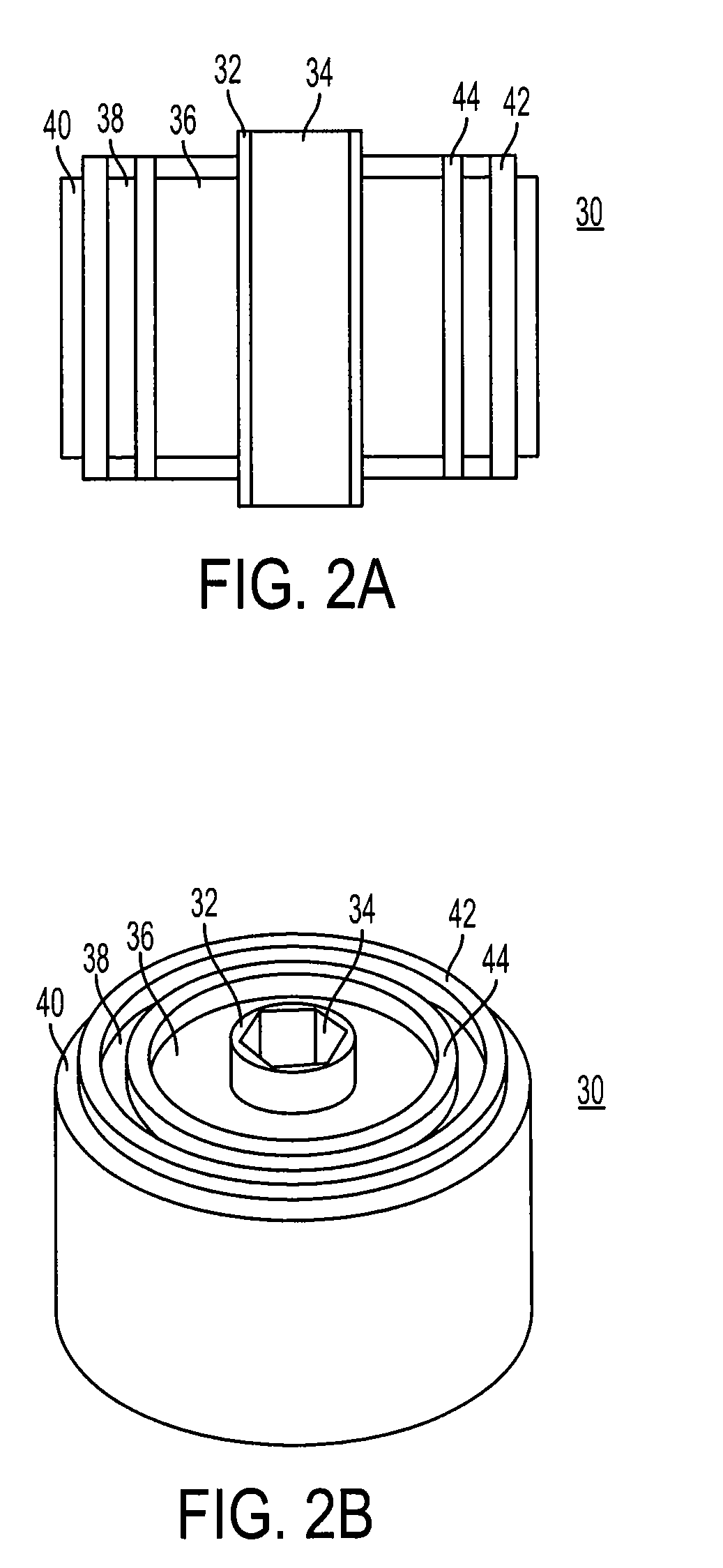
[0035]The film capacitors of the present invention are wound discretely on a small extractable core, or hollow core. They are either finished as discrete single units or assembled as a group and finished as a large unit. Concentric capacitors are wound on top of one another, using the previous capacitor as the new core. In between each active capacitor winding there is an electrically insulating barrier. This barrier varies in extension and thickness between the active capacitors. The dimension of the barrier depends on the electrical insulating criteria needed to satisfy creepage and clearance requirements.

[0036]It will be appreciated that the multiple wound capacitors of the present invention provide several advantages over conventional film capacitors. These include an ultra low equivalent series inductance (ESL), which is due to the close proximity of one capacitor to the other. Another advantage of the present invention is wound film capacitors having significant increases in c...


PUM

PropertyMeasurementUnit
Electrical conductoraaaaaaaaaa
Energyaaaaaaaaaa

Abstract

Multiple wound film capacitors include a hollow core formed by a first non-conducting tubular section, and a first capacitor winding wrapped around the first non-conducting tubular section. Also included are a second non-conducting tubular section wrapped around the first capacitor winding, and a second capacitor winding wrapped around the second non-conducting tubular section. The multiple wound film capacitors may also include a third non-conducting tubular section wrapped around the second capacitor winding, and a third capacitor winding wrapped around the third non-conducting tubular section. In addition, ends of the first and second non-conducting tubular sections extend beyond ends of the first and second capacitor windings.

Description

FIELD OF THE INVENTION[0001]The present invention relates, in general, to wound metallized film capacitors. More specifically, the present invention relates to multiple concentric film capacitors that are wound one on top of another, using a previous capacitor as a new winding core.BACKGROUND OF THE INVENTION[0002]Industry standards for AC and high power DC capacitors have traditionally centered around oil filled capacitor technology. This technology offers benefits of high corona resistance and transient capabilities. Capacitors using this type of technology, however, have problems of potential oil rupture, expensive housings and terminals, poor high frequency response (noisy), mounting restrictions and increased weight. Oil fill technology traditionally employs series disconnects which remove the capacitor from the circuit (or system) by physical distortion of the capacitor housing to break the conductor. These capacitors are permanently disconnected from the circuit and cannot be...

Claims


Application Information

Patent Timeline
IPC IPC(8): H01G2/14H01G7/00H01G4/32
CPCH01G4/32H01G2/14Y10T29/43H01G4/385H01G2/08H01G4/28
Inventor LAVENE, BERNARDCURTO, DAVID
Owner ELECTRONICS CONCEPTS
Why Eureka
Try Eureka