
Liquid-cooled memory system having one cooling pipe per pair of dimms

a technology of memory modules and cooling pipes, applied in the direction of cooling/ventilation/heating modifications, electrical apparatus casings/cabinets/drawers, instruments, etc., can solve the problems of system memory can consume a significant percentage of the total system power and generate a corresponding amount of heat, and component and thermal densities can present significant cooling demands and challenges

Active Publication Date: 2013-08-01
LENOVO GLOBAL TECH INT LTD
View PDF15 Cites 60 Cited by
  • Summary
  • Abstract
  • Description
  • Claims
  • Application Information

AI Technical Summary

Benefits of technology

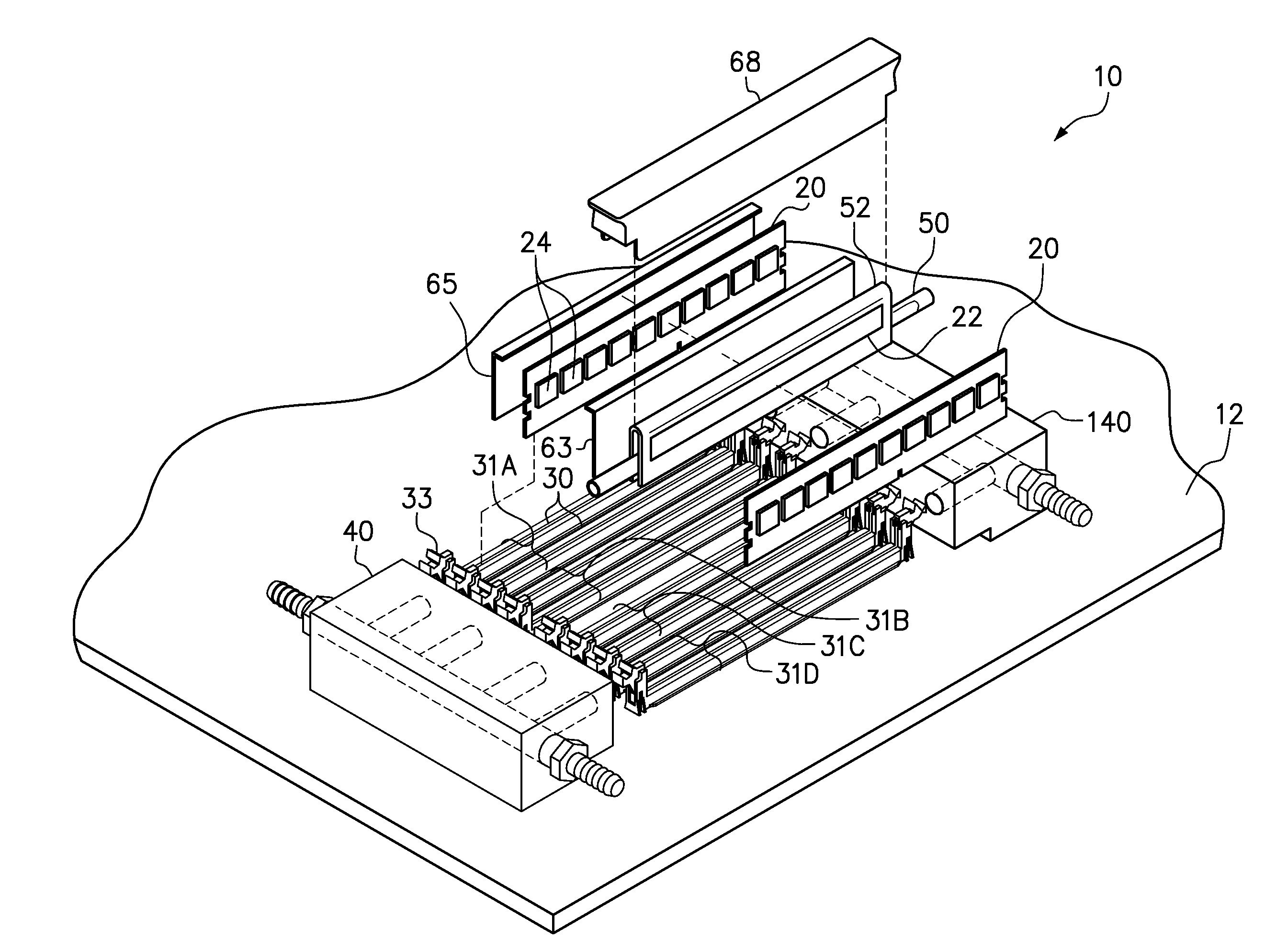
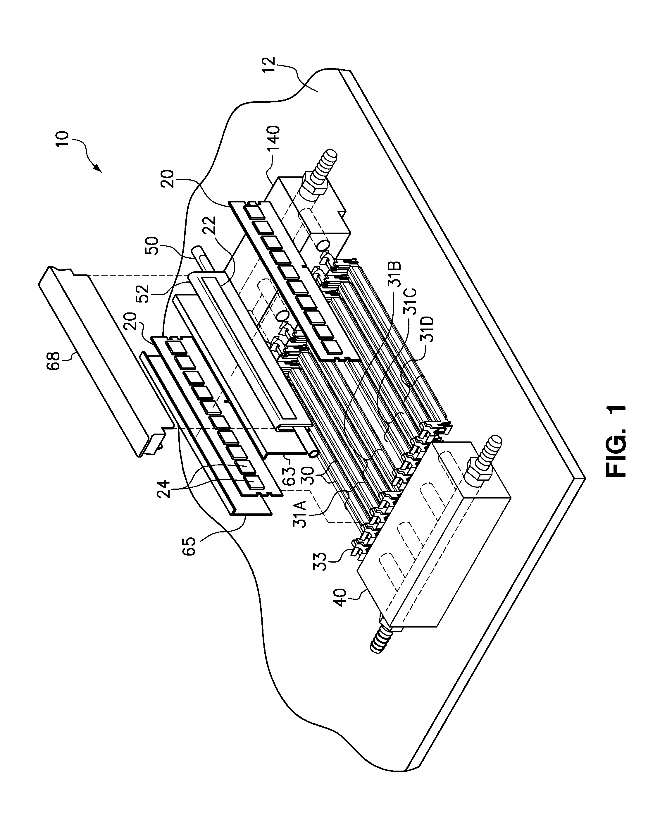
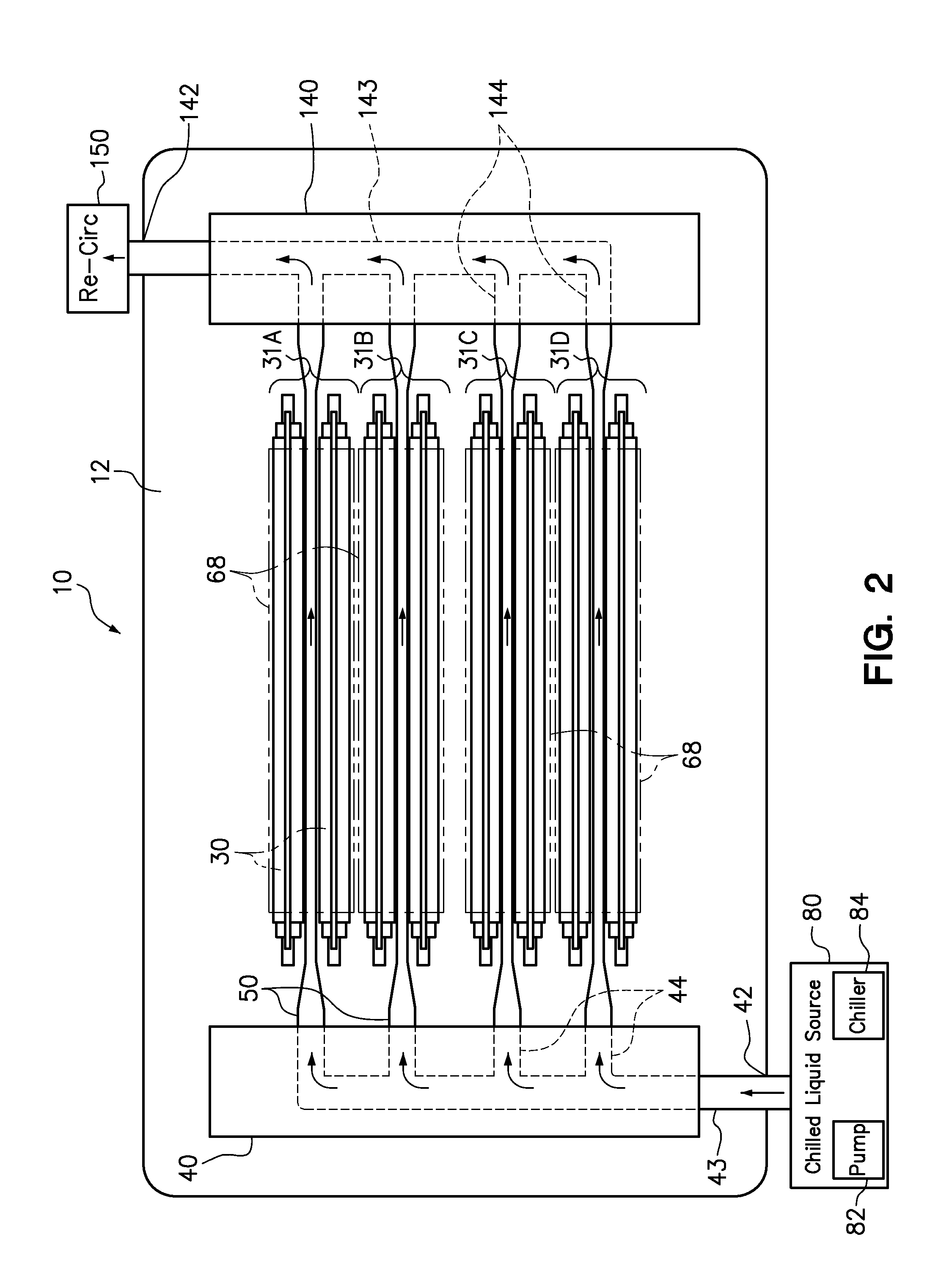
The patent text describes a liquid-cooled computer memory system that includes a plurality of cooling pipes that are connected to a first manifold and a second manifold. Each cooling pipe is positioned between a pair of memory module sockets, with one pair of memory modules on each cooling pipe. A heat spreader is removably positionable on a memory module connected to one of the sockets, with the inner plate of the heat spreader in thermal engagement with the memory module's cooling pipe. The technical effect of this system is improved cooling efficiency and reduction of cooling pipe size.

Problems solved by technology

Computer systems generate heat in relation to their power consumption.
While processors generally have the highest operating temperatures, system memory can consume a significant percentage of the total system power and generate a corresponding amount of heat.
The increased component and thermal densities present significant cooling demands and challenges.
However, compact chassis form factors and high component density leaves only limited space for airflow.
As the density of heat generating components increases, therefore, air cooling solutions are becoming more complicated and costly.
However, current liquid-cooled systems tend to have a higher initial cost and level of design complexity relative to air-cooled systems.
Therefore, existing liquid-cooled system can be cost-prohibitive in some installations.

Method used


Image

  • Liquid-cooled memory system having one cooling pipe per pair of dimms
  • Liquid-cooled memory system having one cooling pipe per pair of dimms
  • Liquid-cooled memory system having one cooling pipe per pair of dimms

Examples


Embodiment Construction

[0016]A cooling system is disclosed that effectively cools memory modules in a memory system using only one cooling pipe for every two adjacent memory module sockets. The example embodiments discussed below use standard dual in-line memory modules (DIMMs) having a plurality of dual random access memory (DRAM) chips. The cooling system includes a liquid cooling loop for circulating chilled liquid (i.e. coolant), and allows for the DIMMs to be easily removed for service from the liquid cooling loop. The cooling pipes are typically liquid flow pipes for passing liquid coolant from a first manifold to a second manifold within the cooling loop. However, in an embodiment with lower DIMM power states, the liquid flow pipe can be substituted with a closed, hollow heat pipe containing a working fluid separate from the coolant circulating through the manifolds. The cooling system includes various heat transfer components for efficiently conducting heat from both DIMMs in a given pair to a sin...


PUM


Abstract

Each pair of memory modules in a memory system are cooled using a shared cooling pipe, such as a heat pipe or liquid flow pipe. An example embodiment includes one pair of memory module sockets on opposite sides of the respective cooling pipe. An inner heat spreader plate is thermally coupled to the cooling pipe and in thermal engagement with a first face of the memory module adjacent to the included cooling pipe. Heat is conducted from the second face of the memory module to the cooling pipe, such as from an outer plate in thermal engagement with an opposing second face of the memory modules and with the inner plate.

Description

BACKGROUND[0001]1. Field of the Invention[0002]The present invention relates generally to cooling computer systems, and more particularly to liquid-cooling computer memory modules.[0003]2. Background of the Related Art[0004]Computer systems generate heat in relation to their power consumption. Cooling systems are used to maintain system components within prescribed temperature limits for operational reliability and safety. System components contribute in varying amounts to the total heat production of a computer system. While processors generally have the highest operating temperatures, system memory can consume a significant percentage of the total system power and generate a corresponding amount of heat. In a server, for instance, memory modules may be responsible for as much as 50% of the total heat load. Increasingly powerful component configurations are being developed for use in pre-defined dimensional constraints. For example, server systems often must conform to existing, st...

Claims


Application Information

Patent Timeline
Patent Type & Authority Applications(United States)
IPC IPC(8): G06F1/20
CPCG06F1/20G06F2200/201
Inventor MEIJER, INGMAR G.SCHMIDT, DEREK I.STEINKE, MARK E.WOMBLE, JAMES S.
Owner LENOVO GLOBAL TECH INT LTD
Learn More