Substrate holder, polishing apparatus, and polishing method

a technology of substrate holder and polishing apparatus, which is applied in the direction of grinding drive, manufacturing tools, lapping machines, etc., can solve the problems of uneven polishing force, lack of polishing or excessive polishing, and “rounded edges" of the edge portion (peripheral portion) of the wafer during polishing, so as to prevent the substrate holder from operating properly

Active Publication Date: 2013-08-01
EBARA CORP
View PDF13 Cites 14 Cited by
  • Summary
  • Abstract
  • Description
  • Claims
  • Application Information

AI Technical Summary

Benefits of technology

[0056]According to the above-described sixth aspect of the present invention, the outer retaining ring is arranged around the inner retaining ring that receives the lateral force from the substrate. In this substrate holder having the inner retaining ring and the outer retaining ring, several sliding parts exist above these two retaining rings, because a torque and a pressing force are transmitted between the two retaining rings through these sliding parts. Wear particles, which could be produced from the sliding parts, may fall onto

Problems solved by technology

When polishing the wafer, if a relative pressing force applied between the wafer and the polishing pad is not uniform over the surface of the wafer in its entirety, lack of polishing or excessive polishing would occur depending on the pressing force applied to each portion of the wafer.
However, since the above-described polishing pad has elasticity, the pressing force becomes non-uniform in an edge portion (peripheral portion) of the wafer during polishing.
Such non-uniform pressing force would result in so-called “rounded edge” which is excessive polishing that occurs only in the edge portion of the wafer.
As a result, the retaining ring cannot apply a desired pressing force to the polishing surface uniformly.
Moreover, the substrate holder disclosed in the above-mentioned patent document has a problem that sliding contact betwee

Method used


Image

  • Substrate holder, polishing apparatus, and polishing method
  • Substrate holder, polishing apparatus, and polishing method
  • Substrate holder, polishing apparatus, and polishing method

Examples


Embodiment Construction

[0098]Embodiments of the present invention will be described in detail below with reference to the drawings. Identical or corresponding parts are denoted by identical reference numerals throughout the views and their repetitive explanations will be omitted.

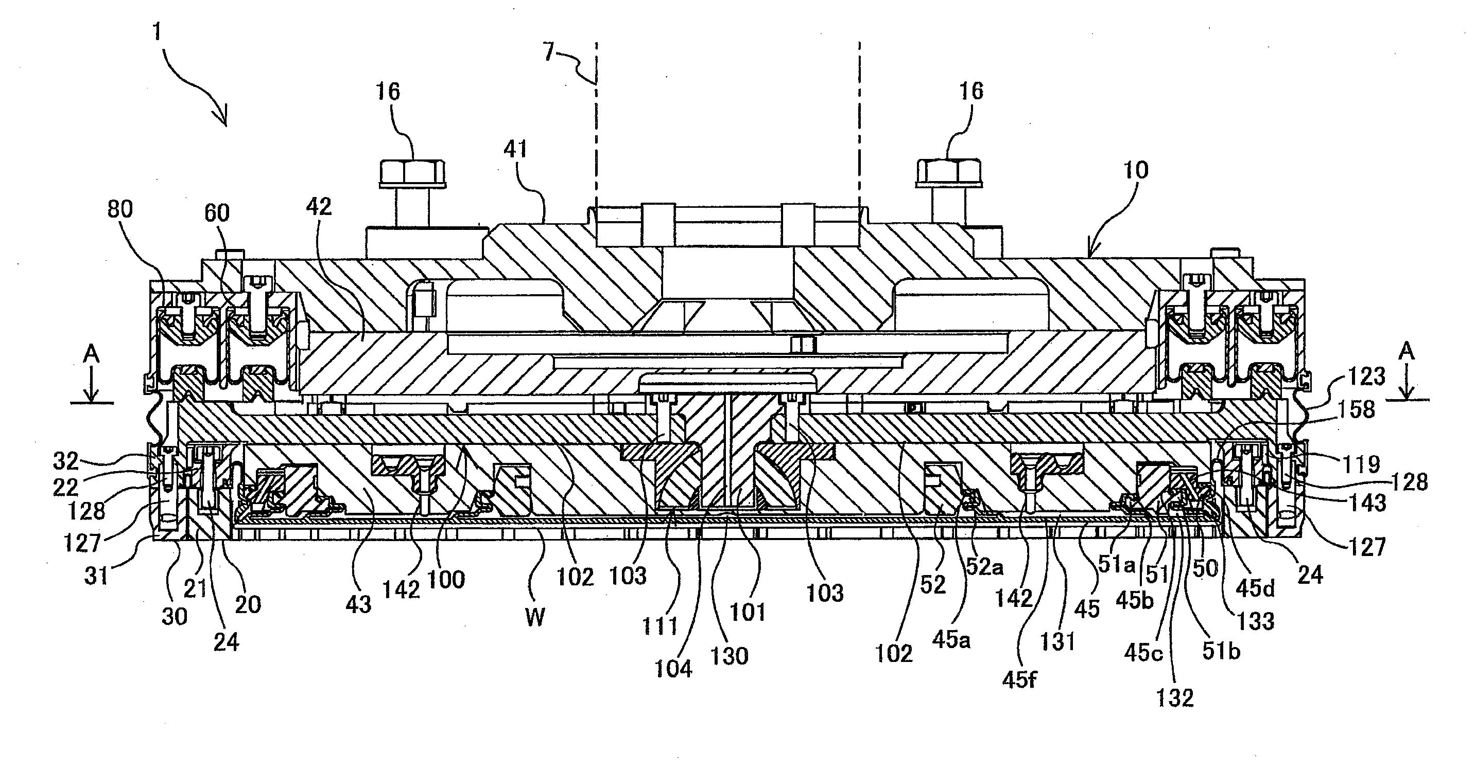
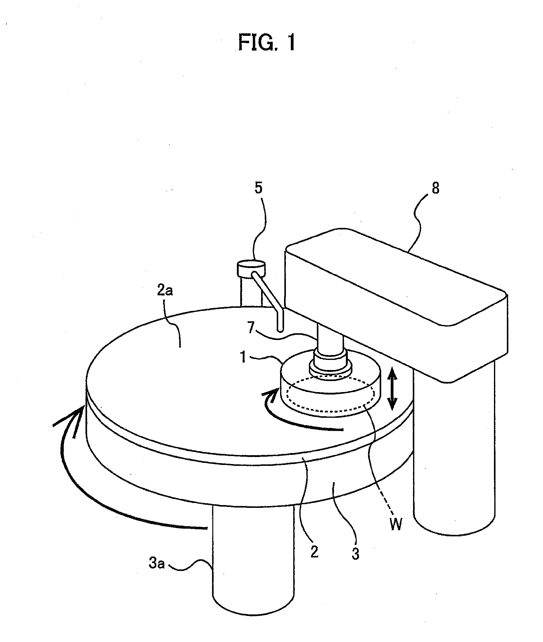
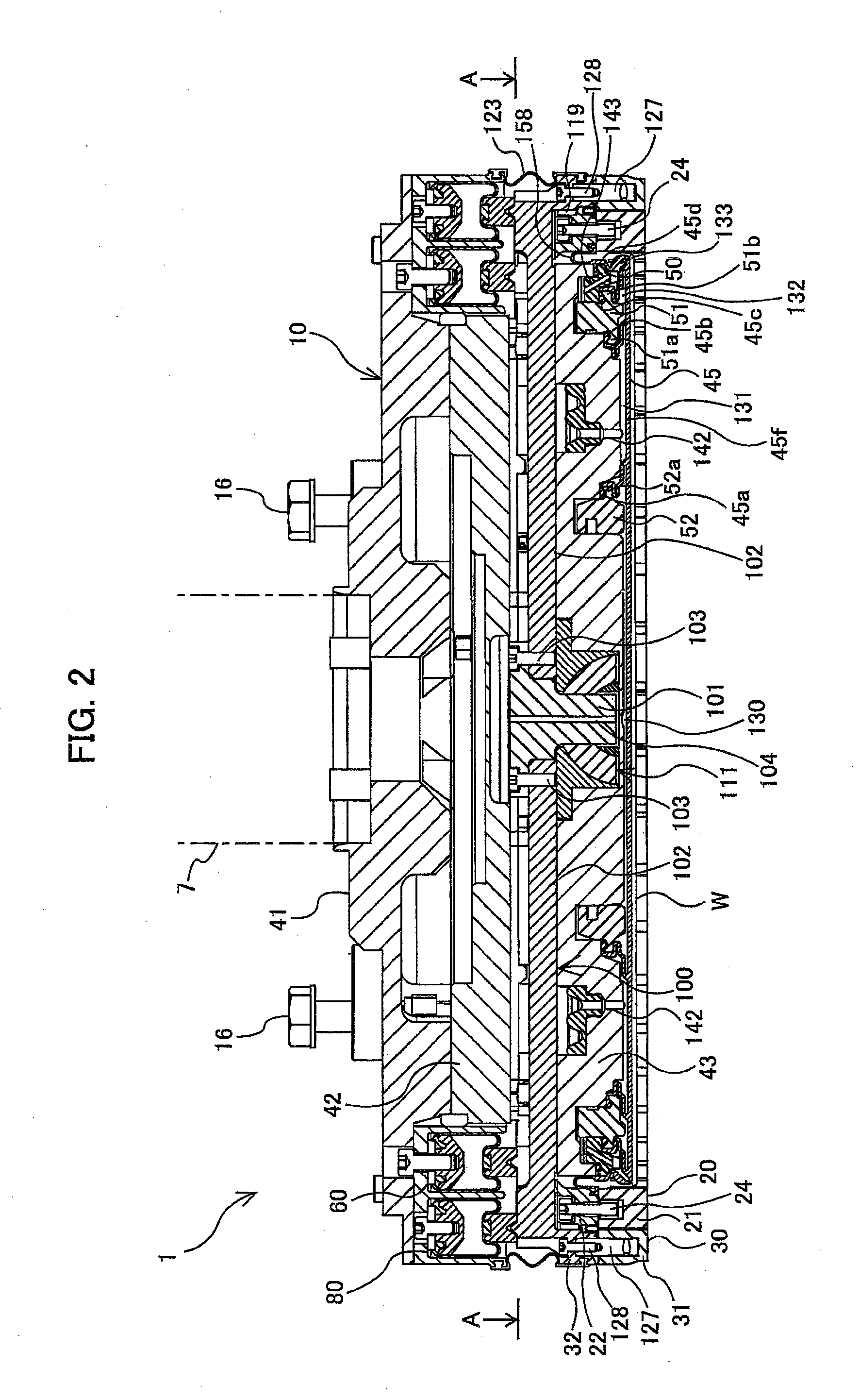
[0099]FIG. 1 is a schematic view of an overall arrangement of a polishing apparatus including a substrate holder (top ring) according to an embodiment of the present invention. As shown in FIG. 1, the polishing apparatus has: a polishing table 3 supporting a polishing pad 2 thereon; and a top ring 1 as a substrate holder for holding a wafer W, which is an object to be polished, and pressing the wafer W against the polishing pad 2.

[0100]The polishing table 3 is coupled to a motor (not shown) disposed therebelow through a table shaft 3a, and is rotated about an axis of the table shaft 3a by the motor. The polishing pad 2, which is attached to an upper surface of the polishing table 3, has an upper surface 2a serving as a polishing s...


PUM

PropertyMeasurementUnit
Forceaaaaaaaaaa
Flexibilityaaaaaaaaaa

Abstract

The substrate holder is a device for holding a substrate and pressing it against a polishing pad. The substrate holder includes: an inner retaining ring vertically movable independently of the top ring body and arranged around the substrate; an inner pressing mechanism to press the inner retaining ring against the polishing surface of the polishing pad; an outer retaining ring to vertically movable independently of the inner retaining ring and the top ring body; an outer pressing mechanism to press the outer retaining ring against the polishing surface; and a supporting mechanism to receive a lateral force applied to the inner retaining ring from the substrate during polishing of the substrate and to tiltably support the outer retaining ring.

Description

CROSS REFERENCE TO RELATED APPLICATIONS[0001]This document claims priorities to Japanese Patent Application No. 2012-18538 filed Jan. 31, 2012 and Japanese Patent Application No. 2012-76677 filed Mar. 29, 2012, the entire contents of which are hereby incorporated by reference.BACKGROUND OF THE INVENTION[0002]1. Field of the Invention[0003]The present invention relates to a substrate holder for use in a polishing apparatus for polishing a substrate, such as a wafer, and more particularly to a substrate holder for holding a substrate and pressing the substrate against a polishing surface. The present invention further relates to a polishing apparatus and a polishing method using such a substrate holder.[0004]2. Description of the Related Art[0005]With a recent trend toward higher integration and higher density in semiconductor devices, circuit interconnects become finer and finer and the number of levels in multilayer interconnect is increasing. In the fabrication process of the multi...

Claims


Application Information

Patent Timeline
IPC IPC(8): B24B37/32B24B37/04
CPCB24B37/32B24B37/30B24B37/042B24B37/04H01L21/304
Inventor FUKUSHIMA, MAKOTOYASUDA, HOZUMINAMIKI, KEISUKENABEYA, OSAMUTOGASHI, SHINGOYAMAKI, SATORU
Owner EBARA CORP
Why Eureka
Try Eureka