Vehicle engine control device

Active Publication Date: 2013-08-01
TOYOTA JIDOSHA KK
View PDF0 Cites 3 Cited by
  • Summary
  • Abstract
  • Description
  • Claims
  • Application Information

AI Technical Summary

Benefits of technology

The patent text describes a method for starting an engine using a power transmission system that reduces the load on the engine during start-up. This is achieved by using a clutch to connect and interrupt power transmission between the engine and the power transmission system. By reducing the rate of inertia of the power transmission system, the load on the engine is reduced, allowing for better engine start-up even at lower engine speeds. The method also improves fuel efficiency and ensures the startability of the engine.

Problems solved by technology

Therefore, a time of execution of fuel cut is problematically shortened, resulting in wasteful fuel consumption.

Method used


Image

  • Vehicle engine control device
  • Vehicle engine control device
  • Vehicle engine control device

Examples


embodiment

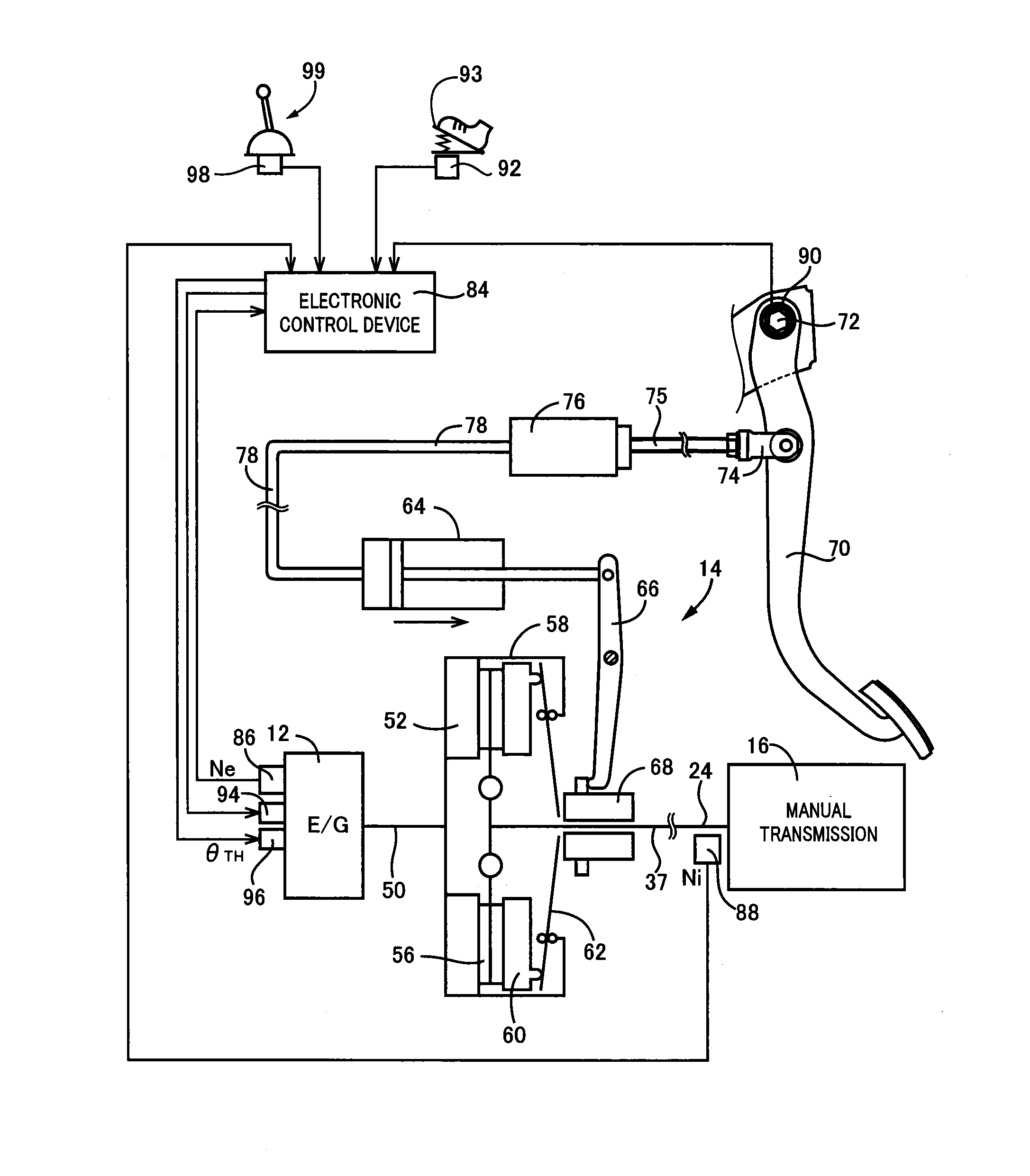
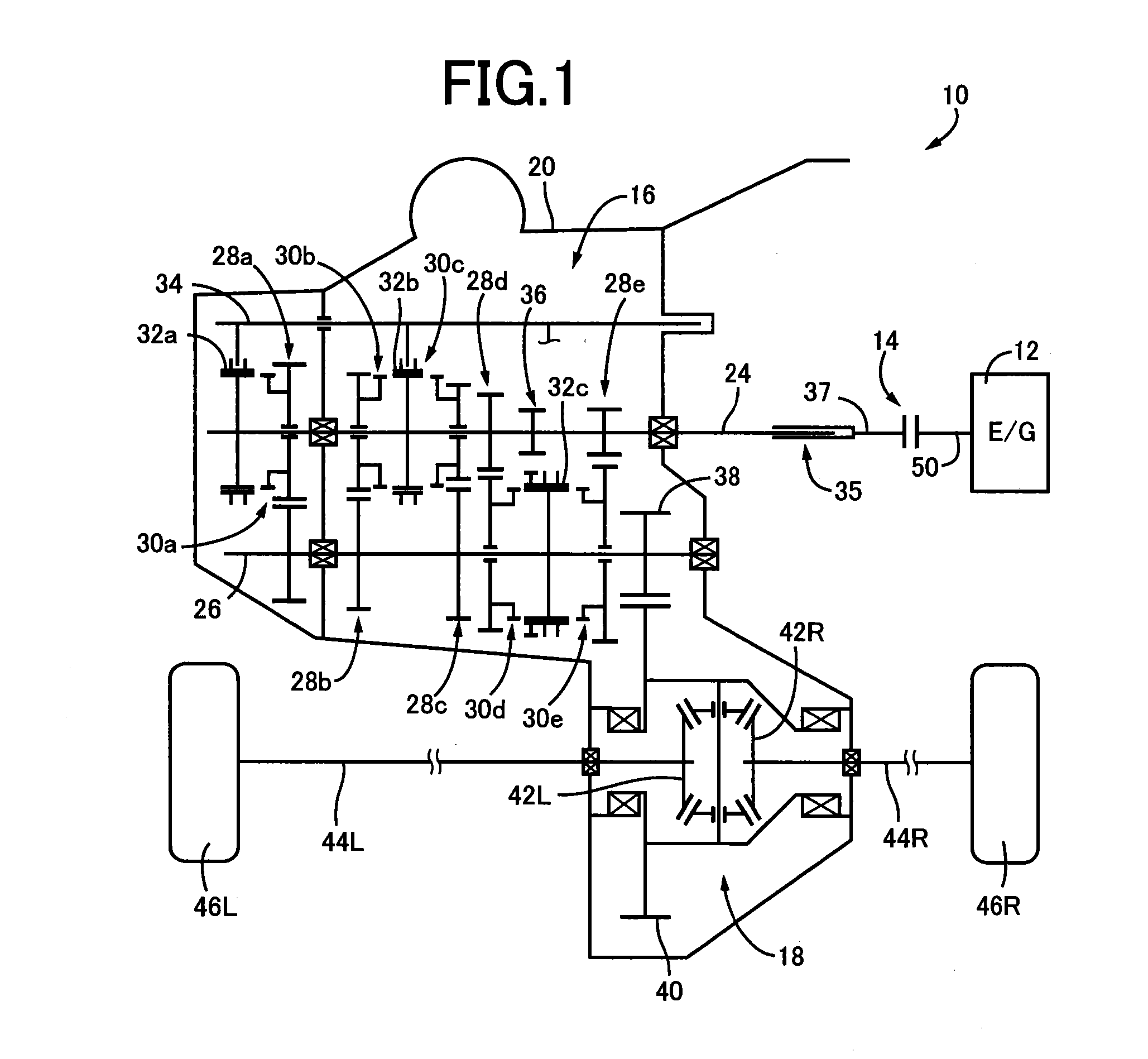
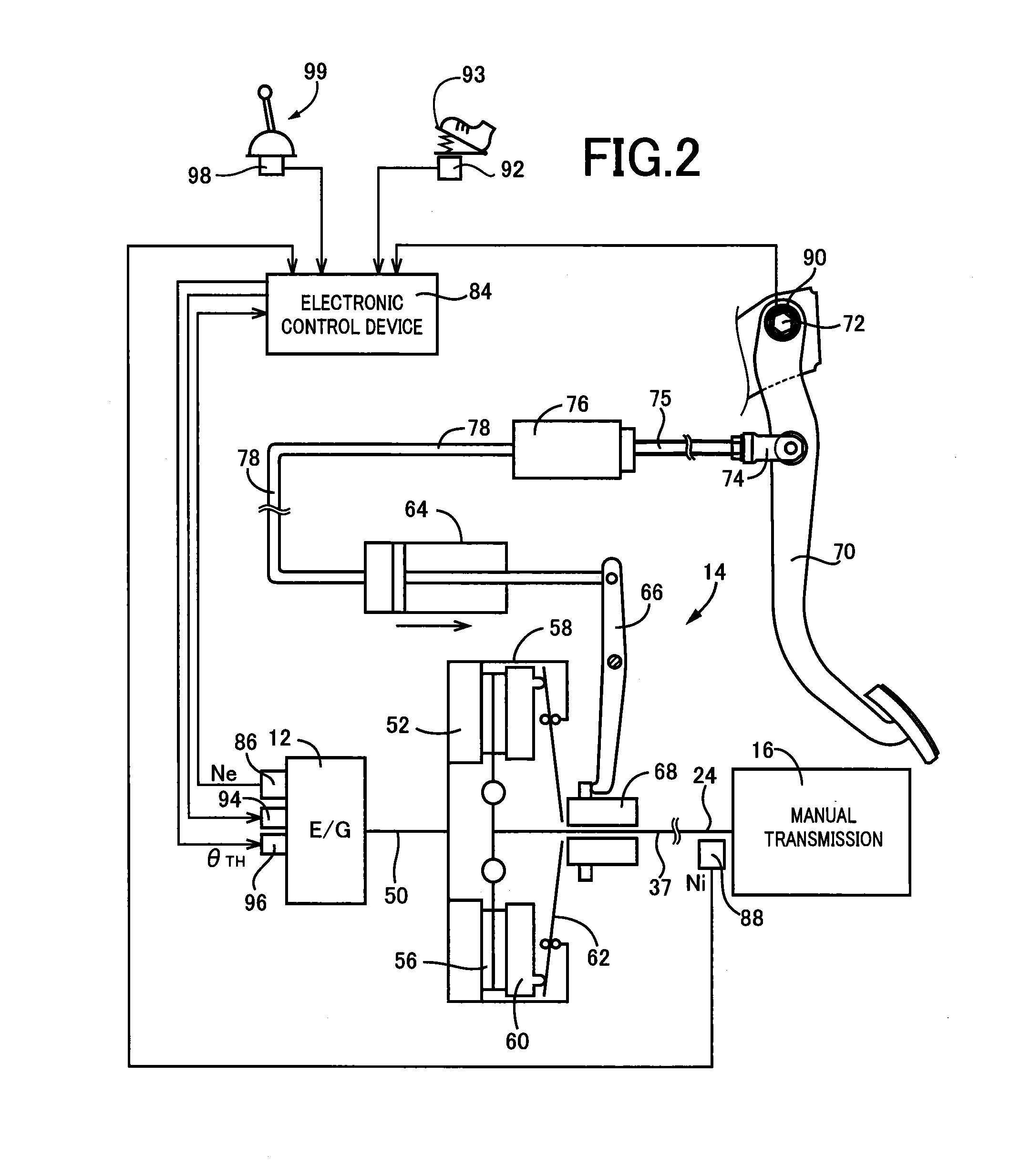
[0025]FIG. 1 is a schematic for explaining a general configuration of a vehicle drive device 10 to which the present invention is applied, and the vehicle drive device 10 is a device for an FF (front-engine front-drive) vehicle and includes an engine 12 as a drive source for running, a clutch 14, a manual transmission 16, and a final reduction gear 18.

[0026]The manual transmission 16 is disposed along with the final reduction gear 18 in a common housing 20 to make up a transaxle and is immersed in lubricant oil infused into the housing 20 by a predetermined amount to be lubricated along with the final reduction gear 18. The manual transmission 16 includes a parallel-shaft-type constant-mesh shifting mechanism having a plurality of constant-mesh change gear pairs 28a to 28e having different gear ratios disposed between a pair of an input shaft 24 and an output shaft 26 in parallel with each other along with a plurality of jaw clutches 30a to 30e corresponding to the change gear pairs...


PUM


Abstract

A vehicle engine control device stopping fuel injection if a predetermined fuel cut condition is satisfied, is provided, during running with the fuel injection stopped, when inertia of a power transmission system rotating with the engine has a smaller rate of inertia of the power transmission system acting on rotation of an output shaft of the engine, the fuel injection being started at a lower engine rotation speed as compared to the case of a larger rate of inertia of the power transmission system acting on rotation of the output shaft of the engine, a clutch capable of connecting and interrupting power transmission between the engine and the power transmission system being interposed between the engine and the power transmission system, a rate of inertia of the power transmission system acting on rotation of the output shaft of the engine being configured to decrease as a clutch stroke of the clutch that is an operation amount of a clutch pedal increases, and an engine rotation speed for starting the fuel injection being set to a lower value as the clutch stroke increases.

Description

TECHNICAL FIELD[0001]The present invention relates to a vehicle engine control device and particularly to fuel cut of an engine.BACKGROUND ART[0002]So-called fuel cut has conventionally been executed that achieves improvement of fuel efficiency by temporarily stopping fuel injection to an engine during deceleration running of a vehicle. For example, one example is an engine fuel supply control device of Patent Document 1. In the technique disclosed in Patent Document 1, if a condition for stopping fuel injection is satisfied in a vehicle including a manual transmission (manual transmission) at the time of shift of the manual transmission, the fuel injection is not immediately stopped after the satisfaction of the condition, and a predetermined delay time is set so as to stop the fuel injection after waiting for the delay time to pass and, particularly, the delay time is set shorter at the time of upshift as compared to the time of downshift. If the delay time is set as described abo...

Claims


Application Information

Patent Timeline
IPC IPC(8): B60W10/02B60W10/06
CPCF02D29/02Y10T477/79B60W10/06B60W10/02F02D41/022F02D41/123F02D2200/101F02D2200/602
Inventor SUZUKI, RYONEGISHI, AKIYOSHITAKEUCHI, SHINICHIKAINO, TAKESHIKOBAYASHI, KATSUYA
Owner TOYOTA JIDOSHA KK
Why Eureka
Try Eureka