Brake control device for vehicle

a technology for controlling devices and brakes, which is applied in the direction of braking systems, instruments, analogue processes for specific applications, etc., can solve the problems of difficulty in reducing the fluid pressure of the wheel cylinder, and achieve the effects of suppressing the vehicle, reducing the driving time and improving the durability of the pressure regulating valv

Active Publication Date: 2013-08-01
ADVICS CO LTD
View PDF6 Cites 11 Cited by
  • Summary
  • Abstract
  • Description
  • Claims
  • Application Information

AI Technical Summary

Benefits of technology

[0010]According to the above configuration, while the vehicle is in a stopped state and the driver is operating the brake operating member (the differential pressure is greater than 0), if the operating amount of the brake operating member increases (typically, a depressing operation to the brake pedal is made), the differential pressure decreases by the increase amount of the basic fluid pressure. In other words, whenever the operating amount increases (whenever the basic fluid pressure increases), the differential pressure decreases. As a result, at the time when the accumulative increase amount of the basic fluid pressure reaches the magnitude of the differential pressure at the stop start timing of the vehicle, it may be possible to make the differential pressure 0 (and thus to stop the driving of the pressure regulating valve).
[0011]As s result, it is possible to reduce the driving time of the pressure regulating valve as compared to a case where the linear electromagnetic valves are continuously driven while the vehicle is in a stopped state and the driver is operating a brake pedal. As a result, the durability of the pressure regulating valve can be improved. Further, when the operating amount increases, the differential pressure decreases by the increase amount of the basic fluid pressure. Therefore, the wheel cylinder fluid pressure (which is the sum of the basic fluid pressure and the differential pressure) does not decrease (or it is difficult for the wheel cylinder fluid pressure to decrease). Therefore, in a case where the vehicle is in a stopped state on a sloping road, it may be possible to suppress the vehicle from slipping down due to an increase in the operating amount.

Problems solved by technology

Therefore, the wheel cylinder fluid pressure (which is the sum of the basic fluid pressure and the differential pressure) does not decrease (or it is difficult for the wheel cylinder fluid pressure to decrease).

Method used


Image

  • Brake control device for vehicle
  • Brake control device for vehicle
  • Brake control device for vehicle

Examples


Embodiment Construction

[0026]Hereinafter, illustrative embodiments of a brake control device for a vehicle will be described with reference to the accompanying drawings.

First Illustrative Embodiment

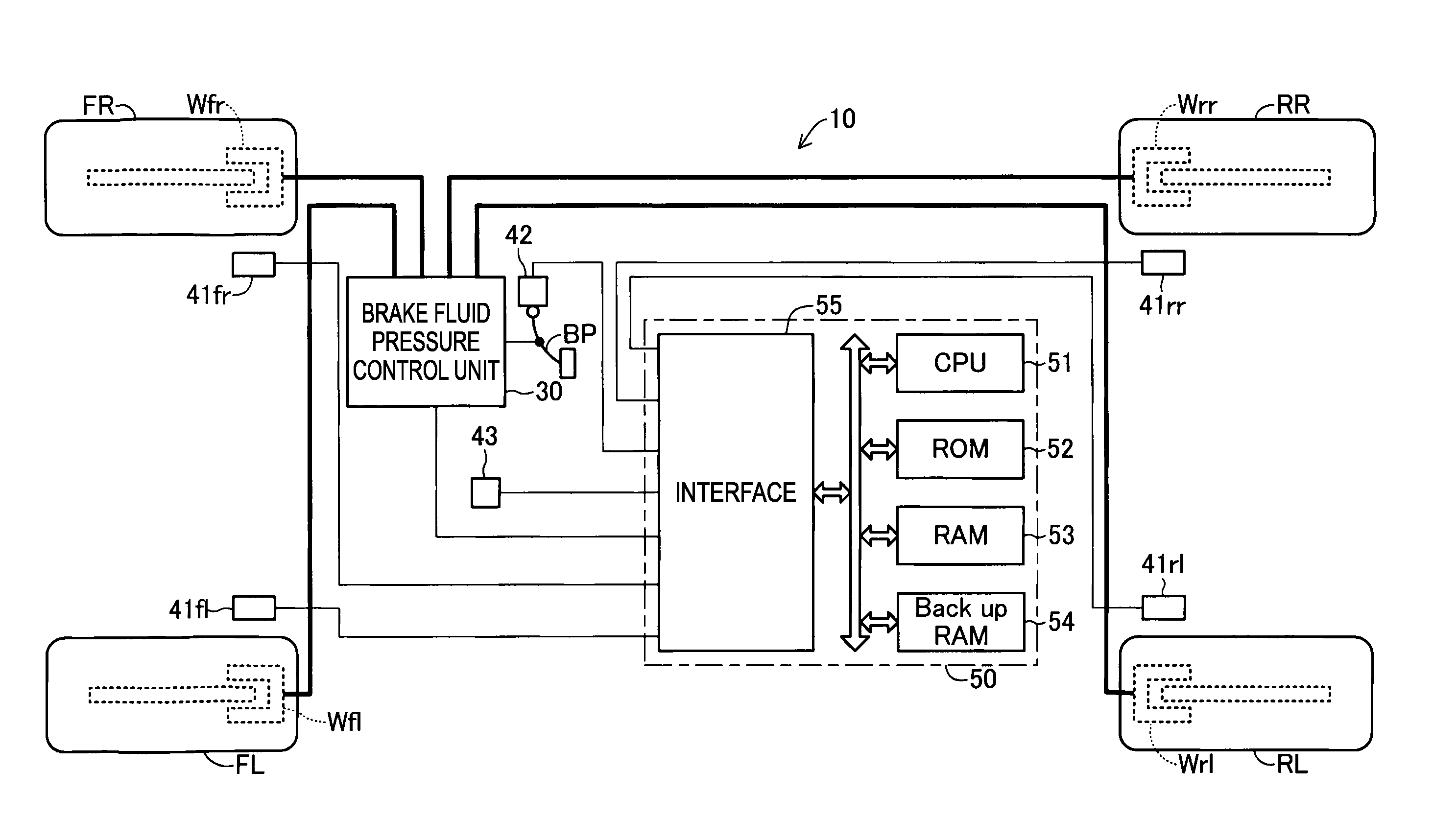
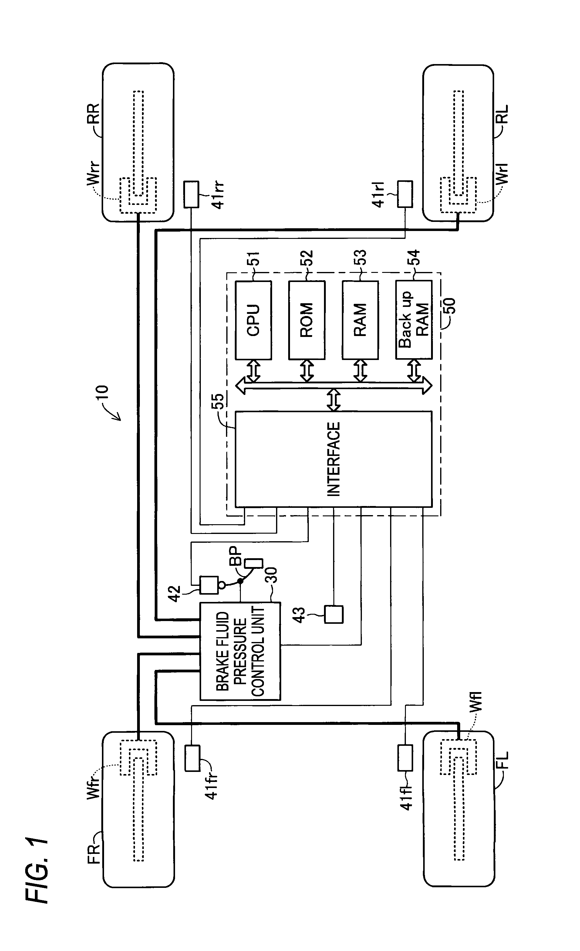
[0027]FIG. 1 shows a schematic configuration of a vehicle including a brake device 10 including a brake control device according to an illustrative embodiment of the present invention. Hereinafter, a symbol ‘**’ added to the ends of various variables and reference numerals is a comprehensive symbol of “fr”, “fl”, “rr” and “rl” which are added to the ends of various variables and reference numerals for representing which of wheels FR, FL, RR, and RL the various variables and reference numerals relate to.

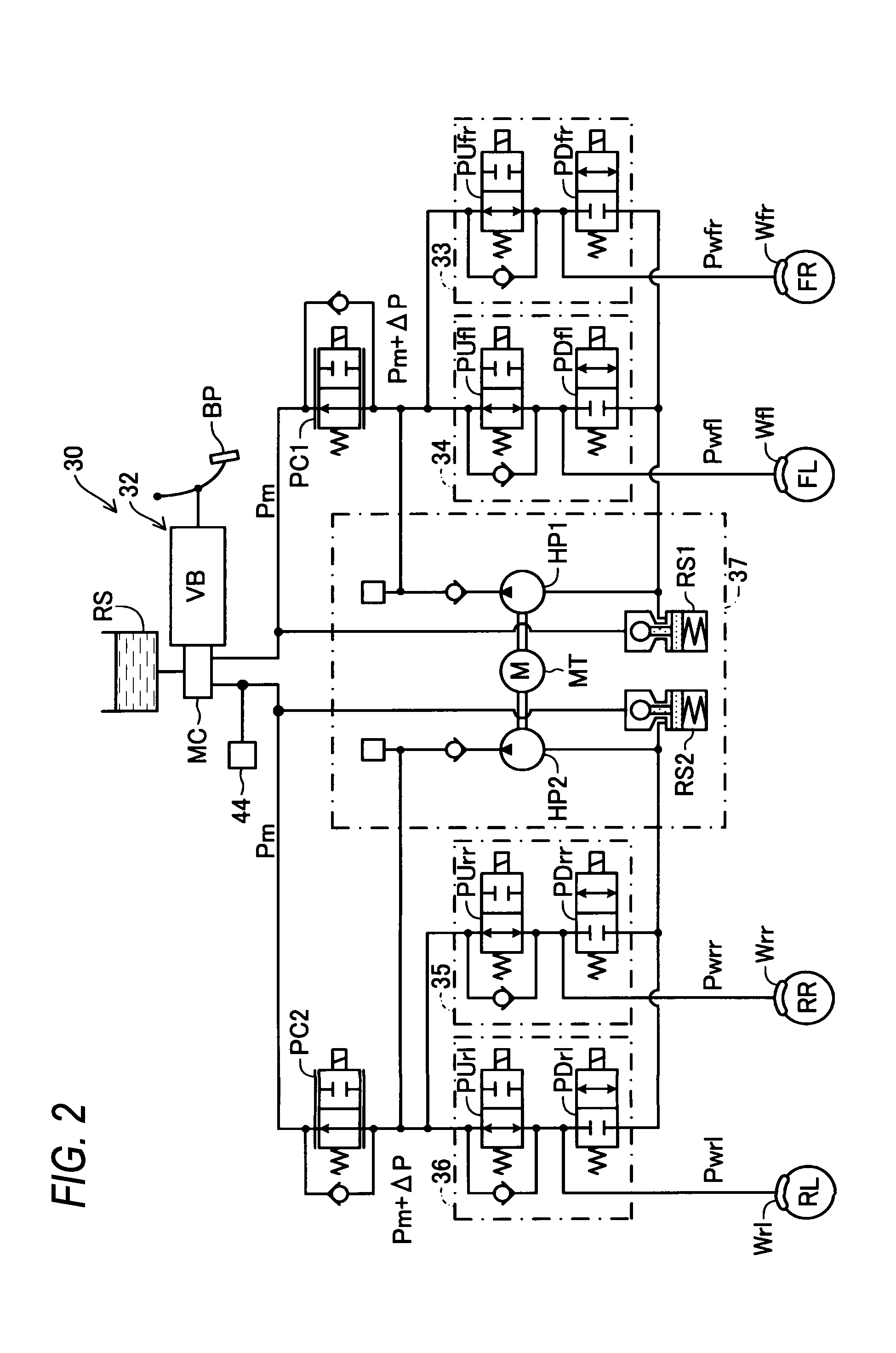
[0028]The brake device 10 includes a brake fluid pressure control unit 30 which generates a friction braking force (friction braking torque) according to a wheel cylinder fluid pressure at wheels**. As shown in FIG. 2, the brake fluid pressure control unit 30 includes a brake fluid pressure generating unit 32 whi...


PUM


Abstract

There is provided a brake control device for a brake device including a basic fluid pressure generating unit which generates a basic fluid pressure according to an operation to a brake operating member, a hydraulic pump which generates a fluid pressure to generate a differential pressure, a pressure regulating valve which regulates the differential pressure, and a friction brake mechanism which applies a fluid pressure obtained by adding the differential pressure to the basic fluid pressure, to a wheel cylinder. The control device includes a regulating unit which regulates the differential pressure according to an operating amount correlated value and which decreases the differential pressure according to an increase of the basic fluid pressure due to an increase of the operating amount correlated value when the vehicle is stopped and the differential pressure is regulated to a value larger than 0 by an operation to the brake operating member.

Description

CROSS REFERENCE TO RELATED APPLICATIONS[0001]This application is based on and claims priority under 35 U.S.C.§119 to Japanese Patent Application 2012-016863, filed on Jan. 30, 2012, the entire content of which is incorporated herein by reference.BACKGROUND[0002]1. Field of the Invention[0003]The present invention relates to a brake control device for a vehicle.[0004]2. Description of Related Art[0005]There has been known a brake device including a master cylinder which generates a basic fluid pressure (master cylinder fluid pressure) according to an operation to a brake pedal by a driver, a hydraulic pump which generates a differential pressure generation fluid pressure to generate a differential pressure (a linear valve differential pressure) to be added to the basic fluid pressure, a pressure regulating valve (normally open linear electromagnetic valve) which regulates the differential pressure using the differential pressure generation fluid pressure, and a friction brake mechani...

Claims


Application Information

Patent Timeline
Patent Type & Authority Applications(United States)
IPC IPC(8): B60T8/34B60T13/14
CPCB60T8/34B60T13/147B60T2201/06B60T8/3655B60T8/4872B60T7/122B60T7/22B60T8/00B60T17/221B60T13/662
Inventor OSAKI, SHINTAROKISO, TAKAHIRO
Owner ADVICS CO LTD
Why Eureka
Try Eureka