Subsea collection and containment system for hydrocarbon emissions

a technology of hydrocarbon emission and containment system, which is applied in the field of subsea collection and containment system for hydrocarbon emissions, can solve the problems of unintended and exponential problems across economic, environmental and societal realms, limited current resources and technologies, and limited availability of extensive required support infrastructur

Active Publication Date: 2013-08-08
BACKES RAYMOND MICHAEL
View PDF11 Cites 25 Cited by
  • Summary
  • Abstract
  • Description
  • Claims
  • Application Information

AI Technical Summary

Problems solved by technology

The longer the delay to respond and provide effective remediation for these situations, may cause unintended and exponential problems across economic, environmental and societal realms.
Current resources and technologies are limited to one incident at a time within the same response area.
This is due to limited availability of an extensive required support infrastructure, the cost, and with few staged deployment locations.
There are a number of small to large scale Oil Spill Response Organizations (OSRO) all with inherent limitations in response times and capabilities.

Method used


Image

  • Subsea collection and containment system for hydrocarbon emissions
  • Subsea collection and containment system for hydrocarbon emissions
  • Subsea collection and containment system for hydrocarbon emissions

Examples


first embodiment

[0114]FIG. 3A is side isometric view of an SSFCE segment 300 including panels 302, support straps 308 and strap termination points 312 for connecting adjacent segments 300. As an example, panels 302 might comprise 500 foot by 100 inch pieces of high-performance reinforced geomembrane such as Seaman XR5 8130 EIA (Ethylene Interpolymer Alloy) Polyester.

[0115]Furthermore the panel material used in the SSFCE segments might also include additional layers or laminations of the same or different material to the interior or the exterior for purposes such as strength and or thermal considerations.

[0116]Those skilled in the art will appreciate that this is just one example, and many variations are possible. For example, the length or diameter of segments 300 may be different. Segment 300 lengths of approximately 500 feet work very well due to fabrication, weight, counter-buoyancy requirements, logistics handling, etc. Longer or larger diameter segments 300 would require an increase in the num...

second embodiment

[0126]FIG. 3E is an isometric view of an SSFCE 300A segment section comprising SSFCE 300 as in FIG. 3D, further including drag coefficient reduction panels 302A and tail flap panels 302B. Construction of SSFCE 300A segments might include the attachment and welding of 302A panels to 302 panels during the construction of SSFCE segment 300A with the subsequent attachment of straps 308 and eyelets 310 and or grommets 310, etc. Panels 302A are the main constituents of the drag coefficient reduction system and panels 302B assist in reducing drag and turbidity, vortex turbulence, etc.

[0127]FIG. 3F is a top view of the segment 300A of FIG. 3E. FIG. 3G is a variation on the segment 300A of FIG. 3E where the drag coefficient reduction panels are connected using both opposing edges of the SSFCE segment (or in some cases opposing edges of two or more SSFCE segments).

[0128]FIG. 3H is a side view of the segment of FIG. 3E.

[0129]FIG. 3I illustrates an embodiment of a SSFCE segment 300, which inclu...

third embodiment

[0139]FIGS. 4E and 4F show a hook-and-loop connection. Loop flaps 303B form a V-shape having loop material disposed on all four sides. Hook flaps 305B form a W-shape having hook material on all six surfaces. Engaging flaps 303B and 305B thus forces water to follow an even more circuitous path in order to leak through this connection. Those skilled in the art will appreciate various other configurations of hook flaps 305 and loop flaps 303 that could form similar connections between SSFCE 502 segments 300.

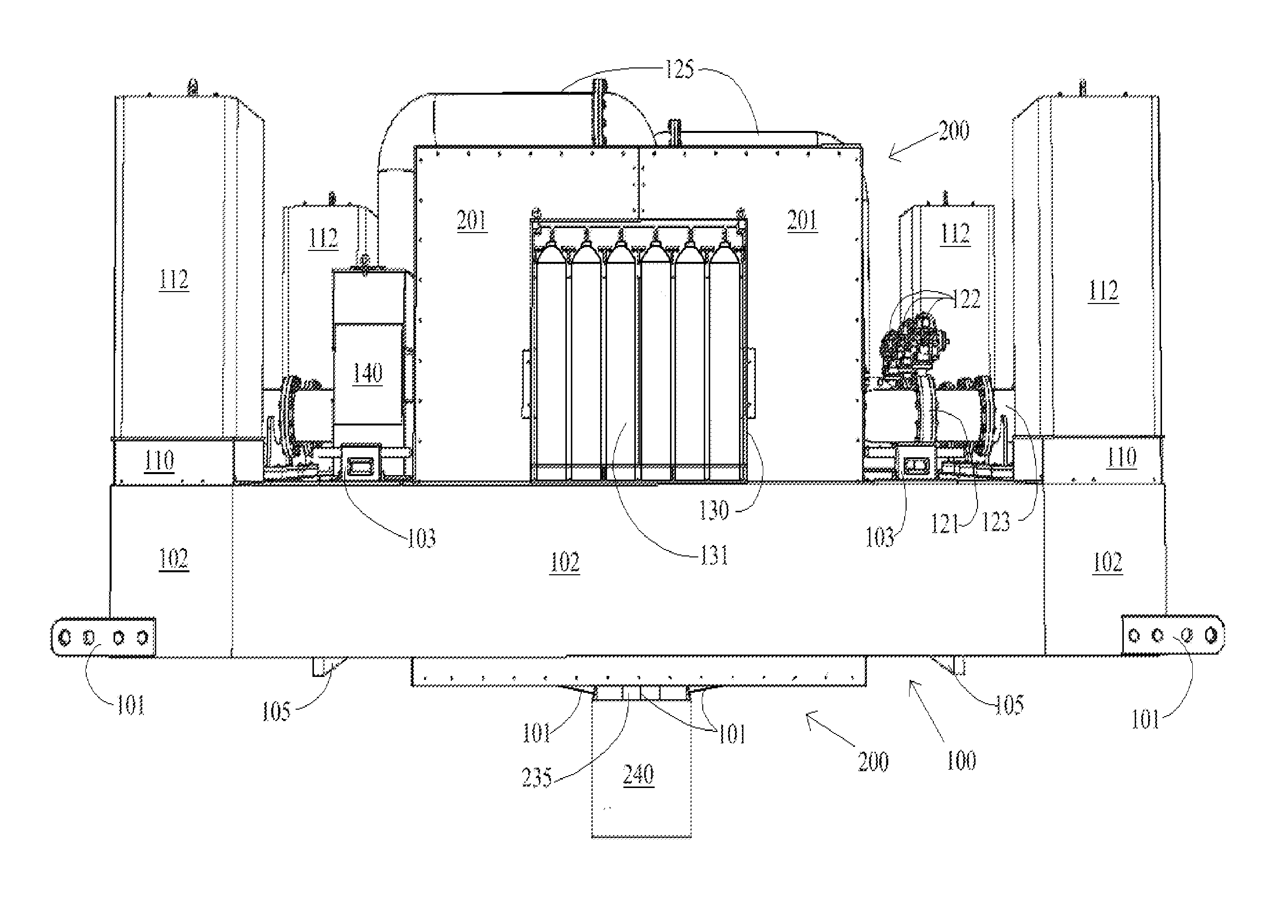
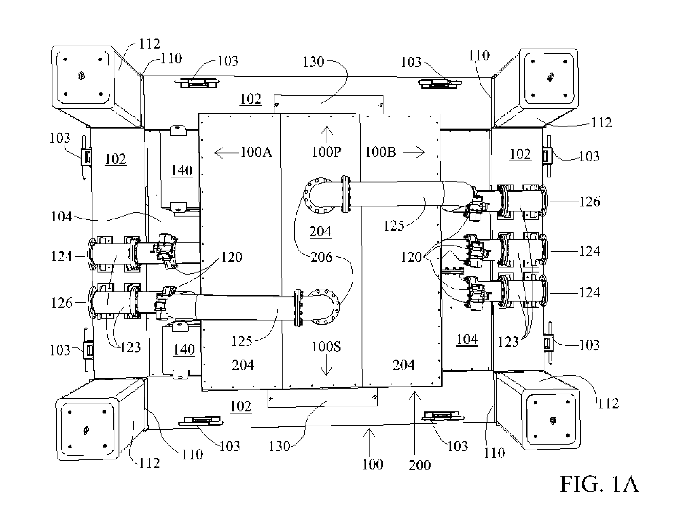
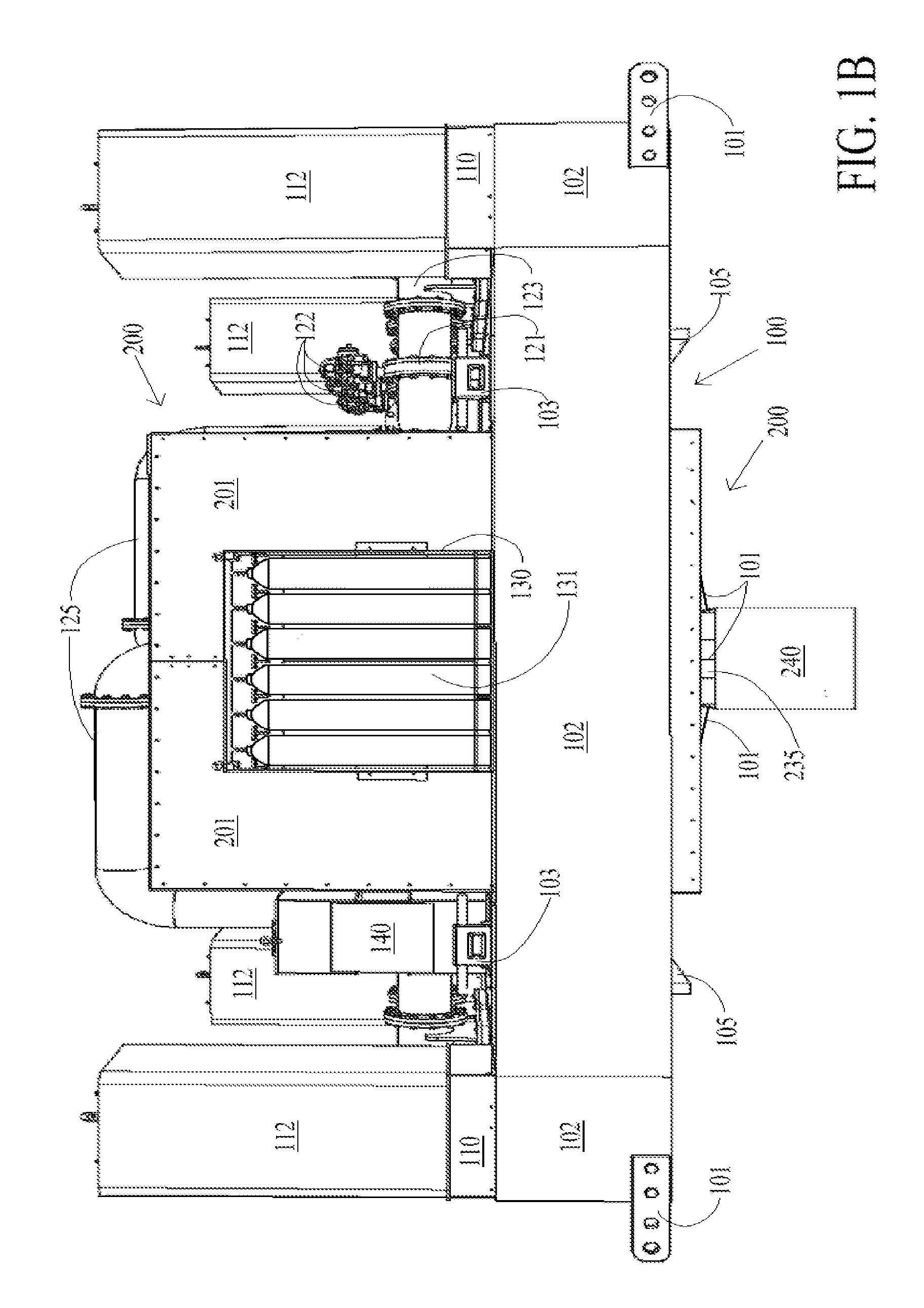
[0140]FIG. 5 comprises FIGS. 5A and 5B which illustrate a deployment configuration of SSFCE 500. FIG. 5 shows how SSFCE 500 connects a hydrocarbon leak to floating platform 100 Rigid Enclosure 200. SSCFE 500 is a self-supporting flexible containment enclosure providing the conveyance method between subsea terminator assembly 600 or canopy terminator 300C and floating platform 100 at sea surface 502. There may be other variations and numbers of SSFCE subsea terminators connected to t...


PUM


Abstract

A rapidly deployable flexible enclosure system for the collection, containment and presentation of hydrocarbon emissions from compromised shallow or deepwater oil and gas well systems, pipelines, other structures, including subsea fissures. The flexible containment enclosure can accommodate various depths and collection terminator configurations. The flexible containment enclosure system is connected to a floating platform and supported by positive offset neutral buoyancy attachment devices. The floating platform with the flexible containment enclosure separates liquid and gaseous materials and directs them to separate ports for removal from a rigid enclosure cavity integrated within the floating platform. Gaseous emissions may optionally be directed to a tethered floating flare system. The system has the ability to partially or fully submerge for extended durations and resurface on demand manually or by transmitted signal. The system provides for operation by a combined tele-supervisory and autonomous control system.

Description

[0001]This application is a continuation in part of U.S. patent application Ser. No. 12 / 853,296, filed Aug. 10, 2010 and incorporates that application by reference.BACKGROUND OF THE INVENTION[0002]1. Field of the Invention[0003]Embodiments of the present invention relate to rapidly deployable flexible enclosure systems for the collection, containment and presentation of hydrocarbon emissions from compromised shallow or deepwater oil and gas well systems, pipelines, and subsea fissures. In particular, the invention relates to such systems used in conjunction with enclosures connected to floating platforms for separating and routing liquid and gaseous hydrocarbon products captured by the enclosure systems.[0004]2. Discussion of Related Art[0005]Oil leakage and or other environmentally sensitive hydrocarbon emissions originating from varied underwater compromised locations, including natural events, need to be addressed quickly and effectively to minimize damage. The longer the delay t...

Claims


Application Information

Patent Timeline
Patent Type & Authority Applications(United States)
IPC IPC(8): E21B43/01E02B15/04
CPCE21B43/0122E02B15/04E21B41/005B63B35/32E21B43/36E21B41/0099
Inventor BACKES, RAYMOND MICHAEL
Owner BACKES RAYMOND MICHAEL
Why Eureka
Try Eureka