Joining method and a punching, stamping rivet

Inactive Publication Date: 2013-08-15
AIRBUS OPERATIONS GMBH
View PDF14 Cites 3 Cited by
  • Summary
  • Abstract
  • Description
  • Claims
  • Application Information

AI Technical Summary

Benefits of technology

The invention introduces a method for joining molded components using a punching, stamping rivet. The method removes disadvantages associated with existing methods and improves vibration resistance. The method includes steps to create a punched hole in the molded components using a polymer material, and to press fit the rivet into the punched hole. The radial widening of the punched hole results in strain hardening and a state of internal stress that prevents the formation and propagation of cracks. The method allows for automatic cold deformation of the punched hole regions, eliminating the need for a separate cold deformation action. The deforming section is designed to ensure smooth injection of material and uniform hardening over the entire length of the punched hole. The combination of conical and cylindrical sections facilitates easier implementation of the deforming section design and further enhances vibration resistance.

Problems solved by technology

A disadvantage of punching, stamping riveted connections is the fact that in comparison to bolted connections they have a relatively low vibration resistance.

Method used


Image

  • Joining method and a punching, stamping rivet
  • Joining method and a punching, stamping rivet

Examples


Embodiment Construction

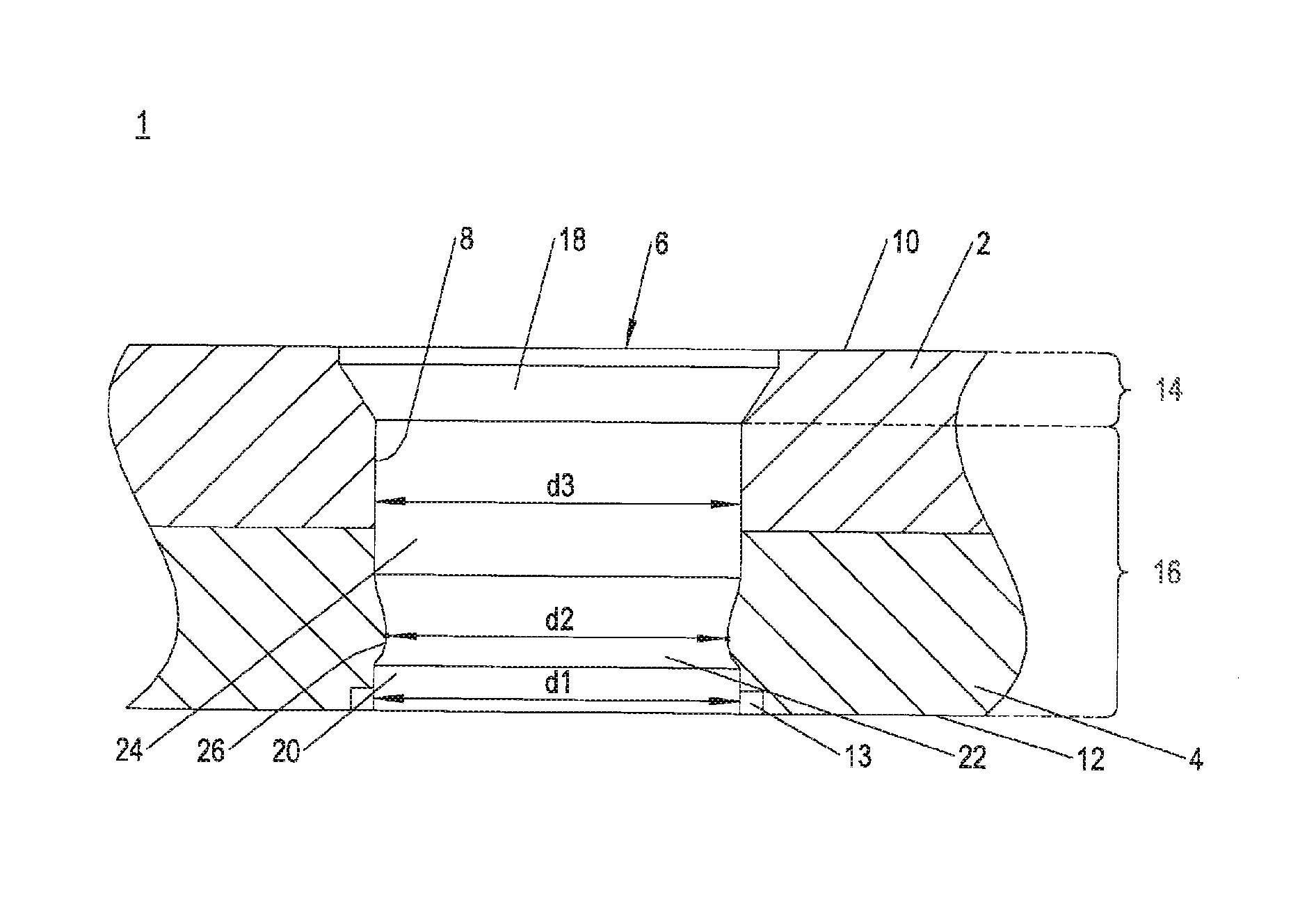
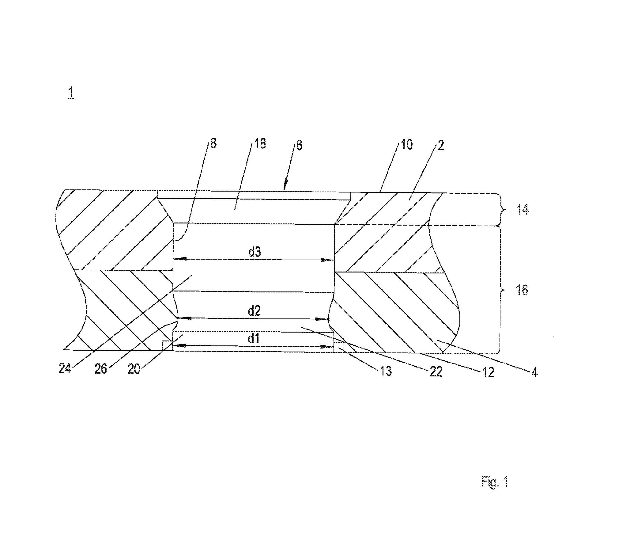
[0021]FIG. 1 shows a joint 1 between two moulded components 2, 4 formed by means of an inventive punching, stamping rivet 6. Needless to say, more than two moulded components 2, 4 can also be joined by means of the inventive punching, stamping rivet 6. The moulded components 2, 4 are designed in the form of plates in the region of the joint 1 and consist in each case of a material that can be cold formed, such as aluminium, magnesium, steel, or an appropriate metal alloy. The punching, stamping rivet 6 is fully accommodated in a punched hole 8 that it has formed, and terminates in the entry region flush with a surface 10 of what is, in accordance with the representation in FIG. 1, the upper moulded component 2. In the exit region of the punched hole 8, i.e. in the region of a surface 12 of what is, in accordance with the representation in FIG. 1, the lower moulded component 4, an embossing ring 13 is formed, which runs coaxially with the axis of the punched hole and is introduced du...


PUM

PropertyMeasurementUnit
Diameteraaaaaaaaaa

Abstract

A method for the joining of moulded components with a punching, stamping rivet, wherein a punched hole is radially widened in at least certain sections of the moulded components that are to be punched. A punching, stamping rivet is provided which has a deforming section that has a greater external diameter than a punching section.

Description

CROSS-REFERENCES TO RELATED APPLICATIONS[0001]This application claims the benefit of the U.S. Provisional Application No. 61 / 598,370, filed on Feb. 14, 2012, and of the German patent application No. 10 2012 202 242.2 filed on Feb. 14, 2012, the entire disclosures of which are incorporated herein by way of reference.BACKGROUND OF THE INVENTION[0002]The invention concerns a method for the joining of moulded components with a punching, stamping rivet and also a punching, stamping rivet for purposes of executing such a method.[0003]A method of known art for the joining of moulded components is so-called punching, stamping riveting with a solid rivet. Punching, stamping riveting often finds application in automotive construction and more generally in the sheet metal processing industry for thin sheets of a very wide variety of metallic materials. Suitable materials are, for example, light metals such as aluminium and magnesium, or ferrous metals such as steel. However, punching, stamping...

Claims


Application Information

Patent Timeline
IPC IPC(8): F16B19/06
CPCF16B19/06Y10T29/49956B21J15/025
Inventor BENSE, ROLFGORR, EUGENJENDRNY, JOERG
Owner AIRBUS OPERATIONS GMBH
Why Eureka
Try Eureka