Inertial micro-sensor of angular displacements

a micro-sensor and angular displacement technology, applied in the field ofinertial movement sensors, can solve problems such as falsehood

Active Publication Date: 2013-08-15
COMMISSARIAT A LENERGIE ATOMIQUE ET AUX ENERGIES ALTERNATIVES
View PDF2 Cites 10 Cited by
  • Summary
  • Abstract
  • Description
  • Claims
  • Application Information

AI Technical Summary

Benefits of technology

[0015]An advantageous effect of the invention is to dispose, on a single electrical output, two detection information signals.
[0034]an additional detector is configured to detect the said Coriolis force.
[0035]The objectives, objects, as well as the characteristics and advantages of the invention will become more apparent from the detailed description of an embodiment thereof illustrated by the following accompanying

Problems solved by technology

Although photolithography has made considerable advances that permit even greater miniaturization, t

Method used


Image

  • Inertial micro-sensor of angular displacements
  • Inertial micro-sensor of angular displacements
  • Inertial micro-sensor of angular displacements

Examples


Embodiment Construction

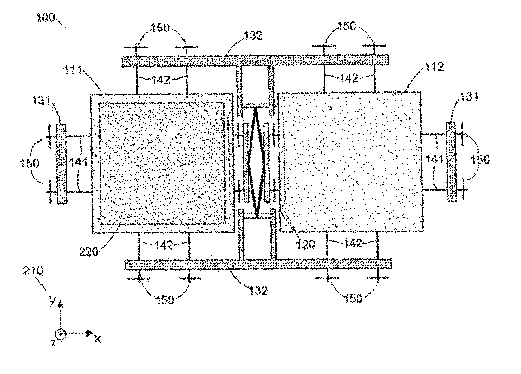
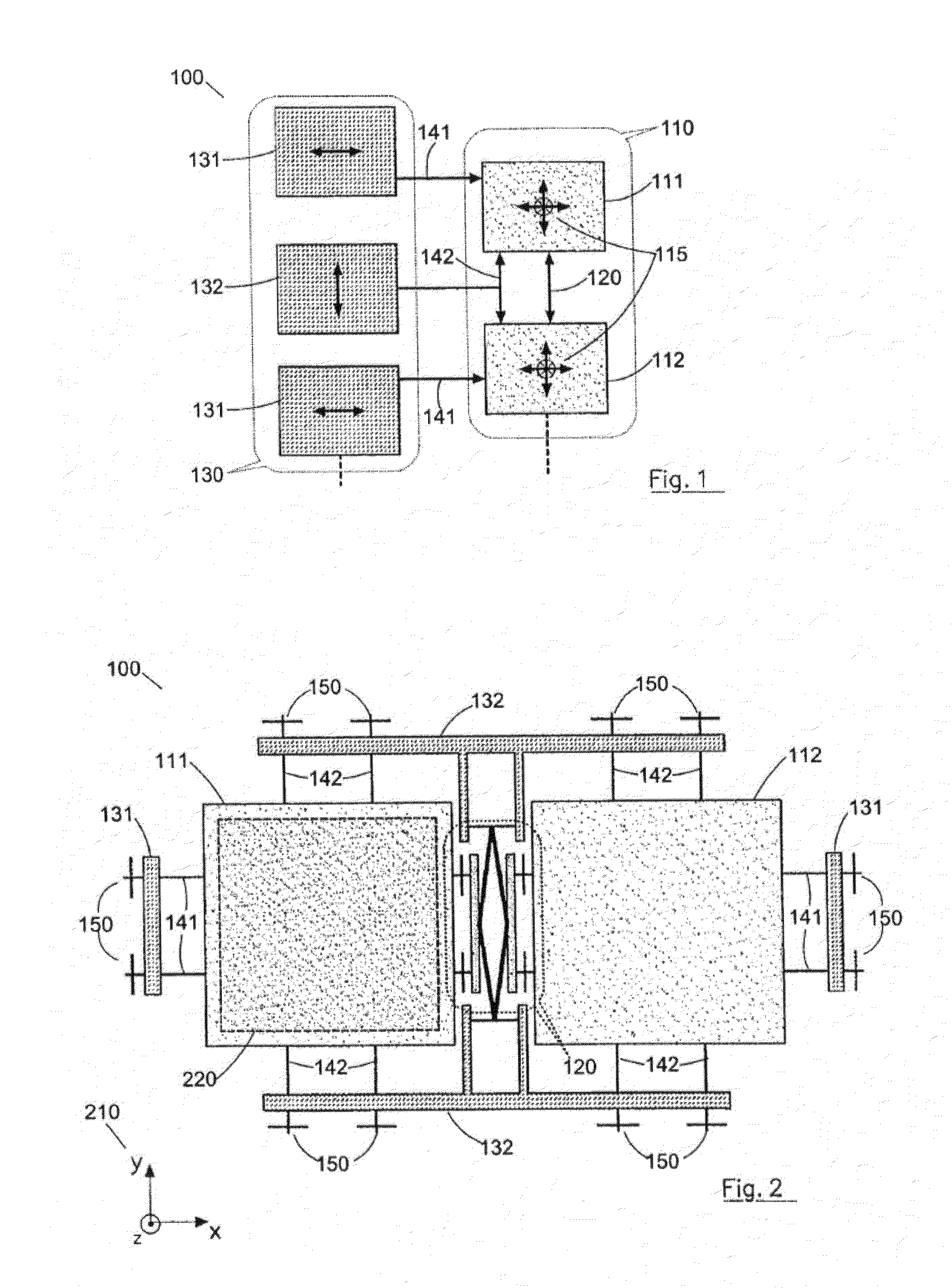
[0050]The invention is able to solve the problem of the surface area occupied by the interconnections of a micro sensor by reducing the number of detectors necessary and more particularly by permitting a given detector to be able to detect several axes simultaneously. The invention is described through the example of a gyrometer comprising a single detector capable of detecting the velocity along several axes.

[0051]The gyrometers considered by the invention are those in which the effect of the Coriolis force is used, which force is expressed in the form of the following vector product:

Fi=−2*m*Ωjυk

[0052]Since the subscripts i, j and k correspond to orthonormal axes, the Coriolis force Fi created is proportional to the inertial mass m and is perpendicular to the angular velocity Ωj and to the excitation velocity νk. An excitation is therefore necessary in order to furnish an excitation velocity. An electrostatic excitation may be written:

νk=V0*cos (wEXC*t)

[0053]The Coriolis force int...


PUM


Abstract

The present invention relates to an inertial micro-sensor of angular displacements comprising at least one inertial mass (112, 1210) movable in space (x, y, z); an exciter (131) configured to generate a first vibratory movement of the inertial mass along a first direction (X) included in the plane (x, y), so as to generate a first Coriolis force induced by an angular displacement of the inertial mass (112, 1210) around a second direction (Y) included in the plane (x, y) and perpendicular to the first direction (X); an exciter (131) configured to generate a second vibratory movement of the inertial mass along the second direction (Y), so as to generate a second Coriolis force induced by an angular displacement of the inertial mass (112, 1210) around the first direction (X), and means for detecting the first Coriolis force and the second Coriolis force, characterized by the fact that the detection means comprise a common detector for the first Coriolis force and the second Coriolis force and configured to produce an electrical signal processed by a processing circuit so as to distinguish a first component of the electrical signal corresponding to the first Coriolis force and a second component of the electrical signal corresponding to the second Coriolis force.

Description

TECHNICAL FIELD OF THE INVENTION[0001]The present invention relates in general to inertial movement sensors and more particularly to those having the form of electromechanical microsystems or MEMS (from the English “Micro Electro Mechanical Systems”).PRIOR ART[0002]Ever since it became known how to construct inertial sensors of very small sizes in the form of MEMS, the English acronym for “micro electromechanical systems”, in other words “electromechanical microsystems”, their area of application has not stopped expanding. At one time reserved almost exclusively for aerial navigation and for ballistic applications, essentially military, of the rockets and missiles type, the inertial sensors, the cost of which has dropped considerably along with their miniaturization, are now commonly employed in very numerous applications characterized as “general public”. For example, they are used for stabilization of video recorder images or of fixed images, camcorders and photographic devices; b...

Claims


Application Information

Patent Timeline
IPC IPC(8): G01C19/5712
CPCG01C19/5712G01C19/5762G01C19/5747
Inventor DEIMERLY, YANNICKJOURDAN, GUILLAUME
Owner COMMISSARIAT A LENERGIE ATOMIQUE ET AUX ENERGIES ALTERNATIVES
Why Eureka
Try Eureka