Passive acoustic barrier

a passive acoustic barrier and vibration-absorbing technology, applied in the direction of air-flow influencers, ceilings, cosmonautic environmental control arrangements, etc., can solve the problems of affecting the payload of vibration-absorbing loads, affecting the payload of composite fairings, and affecting the effect of fairing payloads

Inactive Publication Date: 2010-11-23
THE UNITED STATES OF AMERICA AS REPRESETNED BY THE SEC OF THE AIR FORCE
View PDF43 Cites 42 Cited by
  • Summary
  • Abstract
  • Description
  • Claims
  • Application Information

AI Technical Summary

Benefits of technology

[0030]The present invention includes at least one foam panel attached to a wall associated with a vehicle. At least one capsule containing a liquid and an inertial mass is embedded within the

Problems solved by technology

Vibration and acoustic energy generated by rocket engines are transmitted through the launch vehicle fairing and create severe vibro-acoustic loads that can damage payloads.
However, composite fairings typically have little inherent damping.
The lack of damping results in structural resonances, which are very efficient paths for noise transmission, and are thus deleterious to a fairing payload.
Acoustic blankets are often attached to the inside of fairings to absorb acoustic energy, thereby reducing the overall response in the fairing.
As a result, such blankets do not provide much sound absorption below 250 Hz.
Although acoustic blankets can damp acoustic resonances in the fairing, they do little to alter the structural dynamics of the fairing.
There has been much work to reduce the mechanical path transmission using isolation systems, but little progress has been made to reduce the acoustic path transmission.
The amount of damping added to an acoustic resonance is determined by impedance matching between the material and fluid waves, material thickness, surface area coverage, and the ability of the material to dissipate energy, with the latter being ultimately limited by mass and volume constraints.
This treatment, however, is generally too heavy for a fairing and would not provide as much broadband acoustic absorption as a conventional foam blanket.
Furthermore, viscous elastic treatments are not effective in coupling with low frequency structural resonances and in providing damping.
Such a fluid-filled structure would weigh too much for use in launch vehicle fairings.
While the patent claims “substantial sound absorption at frequencies of less than about 1000 Hz”, it is a fact that as the target frequencies become lower, the volume of the resonators' cavities must become larger to reduce the effective air spring.
Enlarging the volume of the resonators' cavities in accordance with the teachings of this patent would require geometries impractical for fairing applications intended to attenuate acoustic frequencies below 200 Hz.
Also, such resonators are essentially wasted volume at high frequen

Method used


Image

  • Passive acoustic barrier
  • Passive acoustic barrier
  • Passive acoustic barrier

Examples


Embodiment Construction

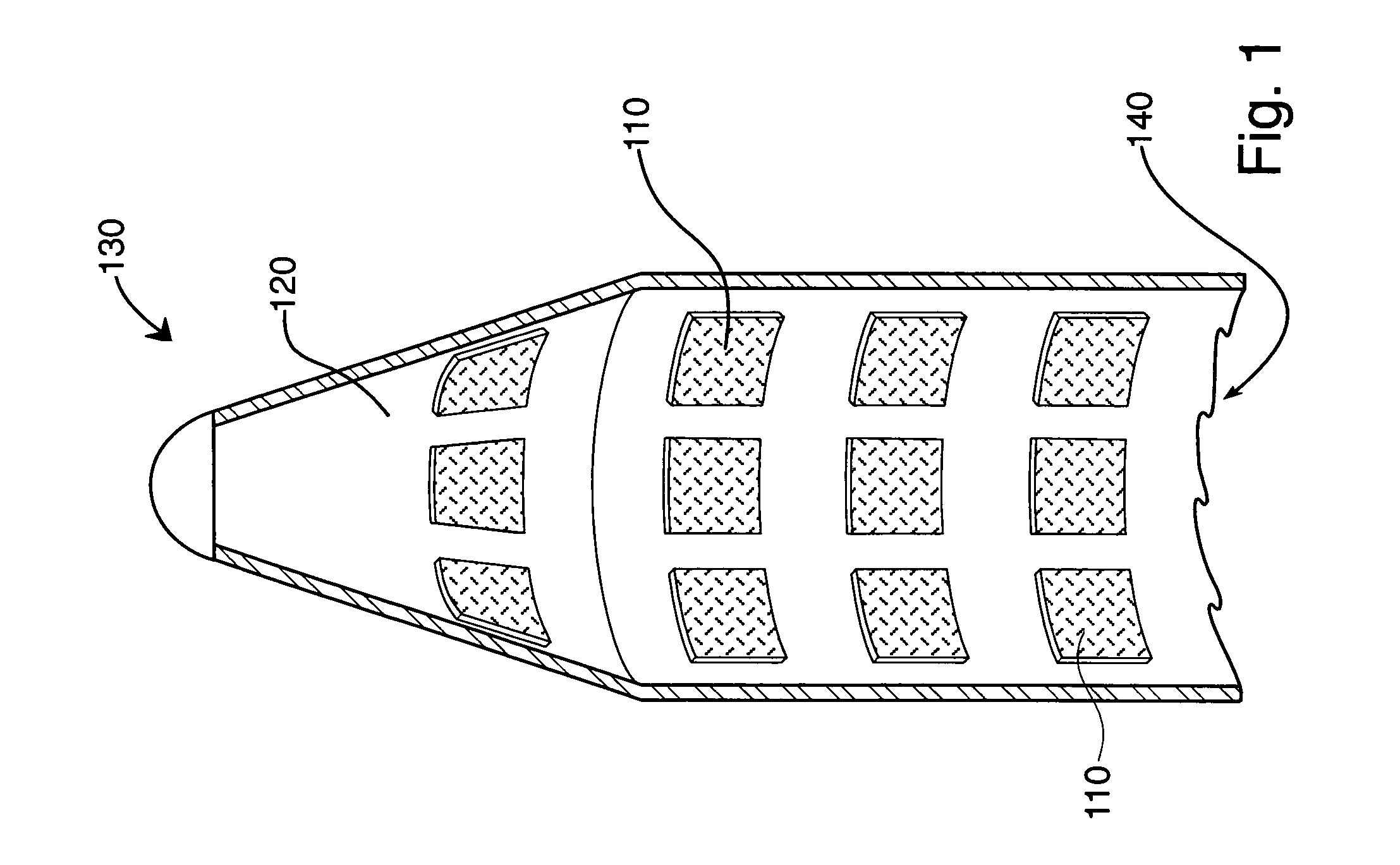
[0045]Turning to the drawings, FIG. 1 illustrates a plurality of acoustic panels 110 of the present invention attached to interior surface of fairing 120 of launch vehicle 130. Panels 110 are shown through random cutouts in fairing 120. Each panel 110 is shaped to avoid interfering with instruments, apparatus, and the payload contained within fairing 120. Panels 110 are comprised of foam adapted to provide broadband dissipation of acoustic energy within volume 140 enclosed within fairing walls 120. The amount of acoustic dissipation is determined by the material properties of the foam, the thickness of the foam, and the total surface area covered.

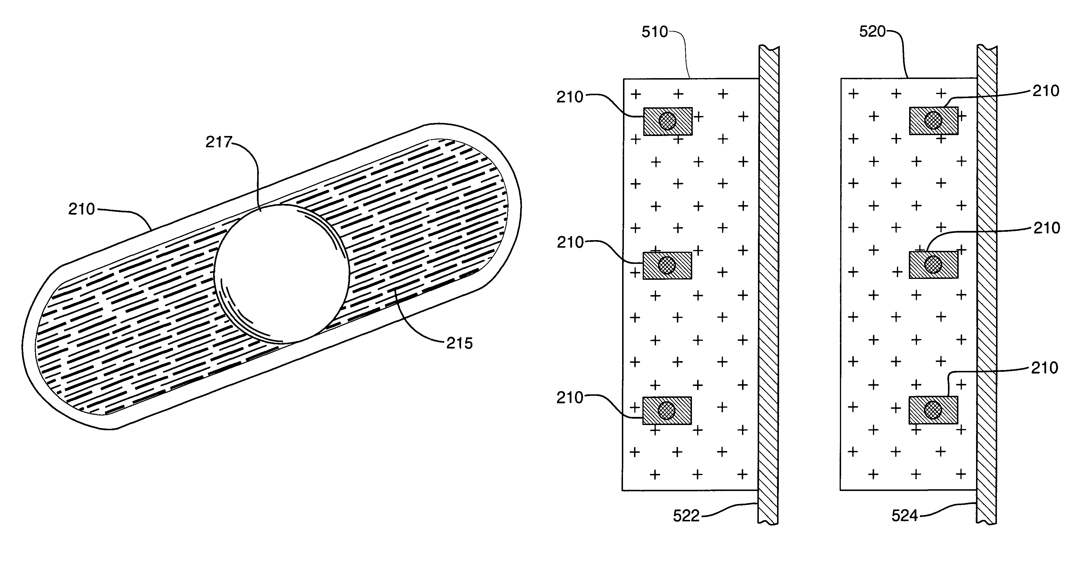
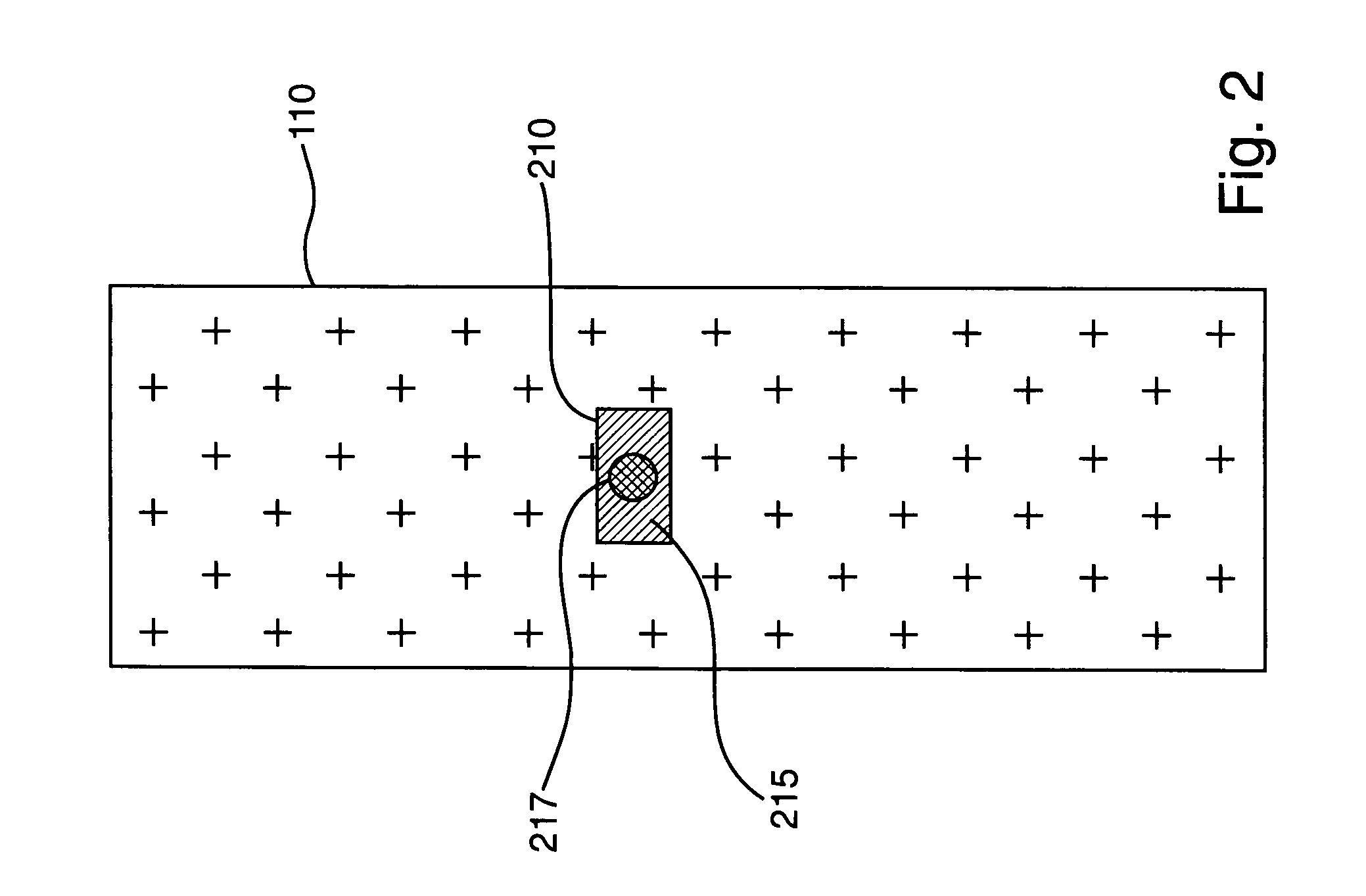
[0046]A cross sectional view of panel 110 is illustrated in FIG. 2. Fluid-filled capsule 210 is embedded in panel 110. Capsule 210 contains fluid 215 and inertial mass 217. Capsules 210 are adhered to panel 110 to keep them in place, but an adhesive may not be necessary, depending on the constraining force applied by the foam material. Caps...


PUM

PropertyMeasurementUnit
Lengthaaaaaaaaaa
Massaaaaaaaaaa
Diameteraaaaaaaaaa

Abstract

A capsule contains fluid and a solid inertial mass that is free to move within the capsule. The capsule is embedded in a foam panel. A plurality of such foam panels are attached to the internal wall of a launch vehicle fairing. This device augments acoustic energy dissipation with damping the resonant frequency of the fairing to reduce the amount of energy that is transmitted into the acoustic volume contained within the wall. Incorporating a plurality of capsules respectively tuned to many frequencies provides broadband structural attenuation. This abstract is provided to comply with the rules requiring an abstract, and is intended to allow a searcher or other reader to quickly ascertain the subject matter of the technical disclosure. It is submitted with the understanding that it will not be used to interpret or limit the scope or meaning of the claims.

Description

[0001]The invention described herein may be manufactured and used by or for the Government of the United States for all governmental purposes without the payment of any royalty.BACKGROUND OF THE INVENTION[0002]This invention relates to mitigating vibro-acoustic energy and, more particularly, mitigating such energy in a launch vehicle payload fairing to reduce the resulting load on the payload and thereby decrease the probability of damage to the payload.[0003]Vibration and acoustic energy generated by rocket engines are transmitted through the launch vehicle fairing and create severe vibro-acoustic loads that can damage payloads. The magnitude of vibration transmitted into the payload volume largely depends on the external noise levels, the mass, stiffness, and damping characteristics of the fairing, and the acoustic damping within the fairing volume. Composite fairings currently being developed are much lighter and stiffer than their metal-alloy predecessors. However, composite fai...

Claims


Application Information

Patent Timeline
IPC IPC(8): F16K17/00
CPCB64G1/22B64G1/38B64G1/46Y10T428/249941
Inventor LANE, STEVEN A.KENNEDY, SCOTT J.ALCONE, JERRY
Owner THE UNITED STATES OF AMERICA AS REPRESETNED BY THE SEC OF THE AIR FORCE
Why Eureka
Try Eureka